Assembling bipolar plates for fuel cells using microencapsulated adhesives

a fuel cell and micro-encapsulation technology, applied in the field of fuel cell bipolar plate assembly, can solve the problems of short pot life of the adhesive, long heat-curing cycle, and inability to meet the requirements of the fuel cell, and achieve the effect of a certain degree of flexibility in the choice of adhesive formulation

Inactive Publication Date: 2015-08-11
BALLARD POWER SYSTEMS
View PDF4 Cites 3 Cited by
  • Summary
  • Abstract
  • Description
  • Claims
  • Application Information

AI Technical Summary

Benefits of technology

[0013]In a preferred embodiment, the profiles of the anode and cathode flow field plates are designed such that a gap exists at the sealing surfaces between the plates when the coolant flow field sides of the plates are mated together in alignment. While not essential for adhesive function, this allows for tight control of the thickness of the overall assembly. If so, the method preferably comprises selecting a microencapsulated adhesive in which the mean diameter of the microcapsules comprising the adhesive is greater than the nominal height of the gap. This selection attempts to ensure that the encapsulant is ruptured when the plates are pressed together. In this regard, it can be advantageous to select a microencapsulated adhesive in which the mean diameter of the microcapsules is greater than twice the nominal height of the gap (e.g. greater than about 1.5 mm for modest gap sizes). Alternatively, the nominal height of the gap can be chosen to be less than about 1.1 mm. Importantly, a suitable bond and seal can be achieved when the nominal width of the sealing surfaces is less than about 6 mm.
[0014]The method allows for some flexibility in the choice of adhesive formulation. For instance, because air is generally excluded from the encapsulated resin until the encapsulant is burst open, formulations might be used which would otherwise have too short of a pot life (e.g. single component epoxies). A suitable adhesive for use as an encapsulated adhesive therefore is a single component epoxy. A double component epoxy may also be employed for instance by applying amounts of two different microencapsulated adhesives in a desired ratio wherein the two different microencapsulated adhesives are the two components of the double component epoxy. Alternatively, each of the two different microencapsulated adhesives could be applied to a different one of the two plates to be joined, such that the two components mix on the bursting of the encapsulant.

Problems solved by technology

However, there are several problems with using such adhesives.
For instance, pot life of the adhesive can be short, so any equipment that is directly exposed to the adhesive during the application process must be cleaned periodically with strong solvents to prevent adhesive from curing on the equipment.
Further, heat-curing can involve a lengthy, energy intensive thermal cycle.
Alternative curing methods can also be problematic.
For instance, UV curing is difficult because the adhesion joints are not externally visible.
And anaerobic curing can be inhibited by the carbon plate materials themselves (typical adhesive resins require metallic ions present to initiate curing, but such ions are otherwise undesirable in the fuel cell).
Such fixtures must remain dimensionally stable over multiple thermal cycles, and this can be a challenging requirement.
And additionally, the material properties of the adhesive can radically change between the time of application and the time of curing with undesirable consequences (e.g. the viscosity may significantly reduce as the glue is heated and run out of the joint or spread via capillary action across the parts and onto the fixtures used to locate and press the plates during curing).

Method used


Image

  • Assembling bipolar plates for fuel cells using microencapsulated adhesives
  • Assembling bipolar plates for fuel cells using microencapsulated adhesives
  • Assembling bipolar plates for fuel cells using microencapsulated adhesives

Examples


example

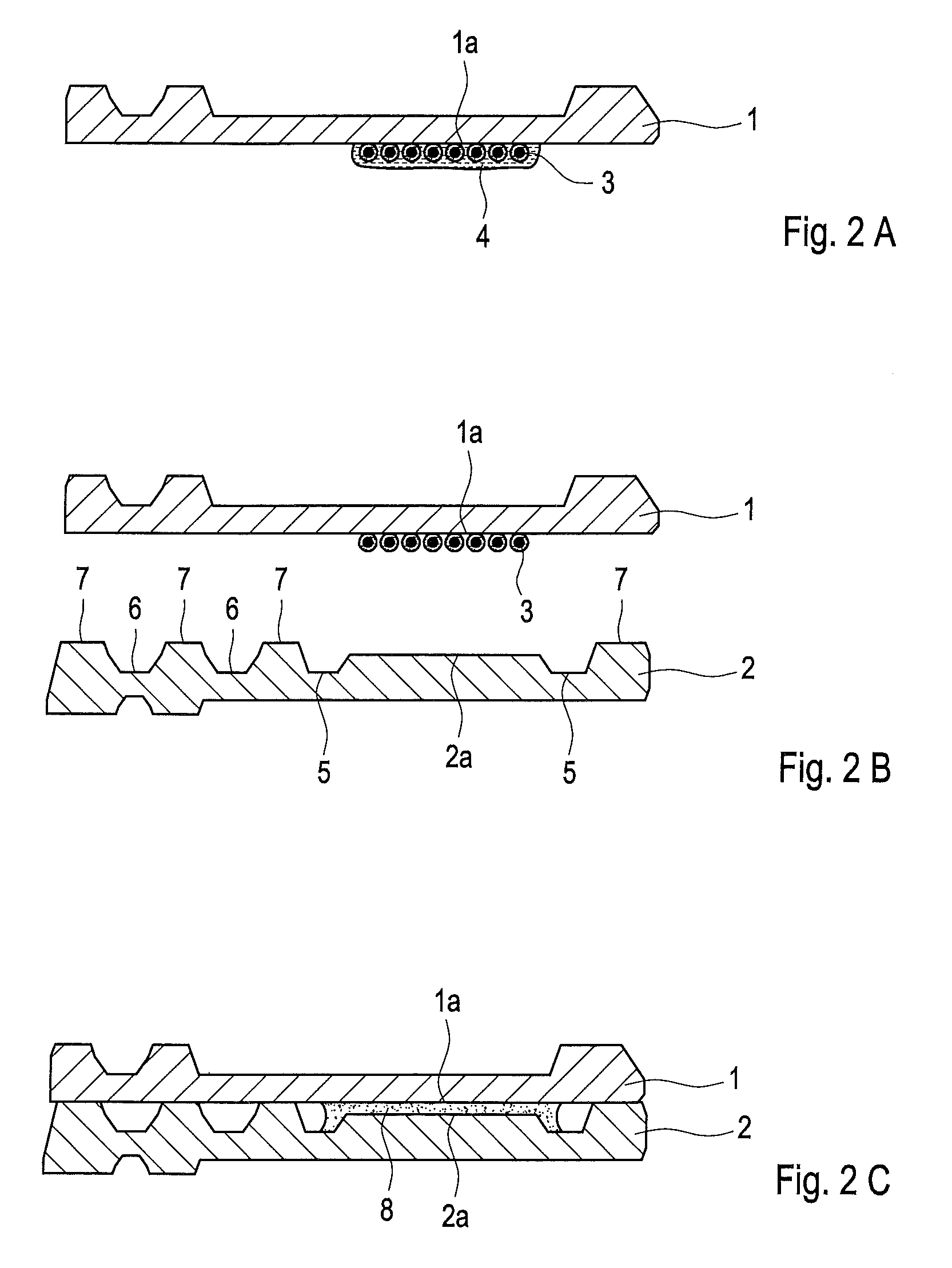
[0037]A series of experimental fuel cell plates were assembled into bipolar plate assemblies using microencapsulated adhesives and the seal integrity was tested using pressurized fluids.

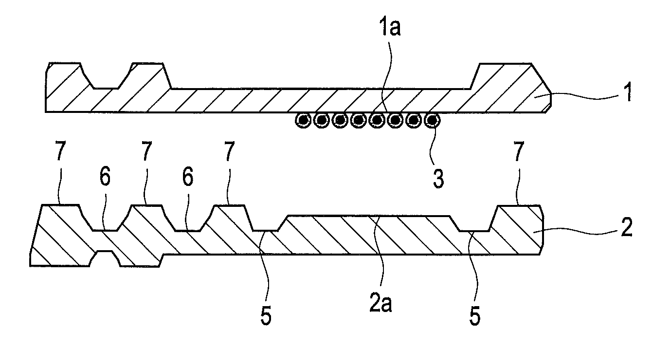
[0038]Square molded carbon composite plates from Nisshinbo (about 12 cm per side) were used. In each assembly, a flat circular groove (about 10 cm in diameter and having ample oversize width in all cases, but having varied groove depths) was machined in one plate in order to create sealing surfaces with varying width and depth. A central port and cross shaped grooves were also formed within the circular sealing groove to allow pressurized test fluid to access the sealed space within the assembly. The other plate in the assembly was left alone and thus was flat and featureless.

[0039]The microencapsulated adhesive used in all cases was Microlock™, a single component epoxy based adhesive in an aqueous carrier from MicroTek. The microencapsulated adhesive beads had a mean diameter of about 0.15 mm.

[0040]...


PUM

PropertyMeasurementUnit
mean diameteraaaaaaaaaa
heightaaaaaaaaaa
widthaaaaaaaaaa

Abstract

The flow field plates in a bipolar plate assembly for a fuel cell can be both bonded and sealed appropriately using microencapsulated adhesives. This offers several advantages over using other adhesives which may have limited pot life and / or require lengthy curing periods at elevated temperature during which time the plates must be stably positioned and under compression.

Description

BACKGROUND[0001]1. Field of the Invention[0002]This invention relates to bipolar plate assemblies for fuel cells and particularly to methods for bonding and sealing the component plates together.[0003]2. Description of the Related Art[0004]Fuel cells such as solid polymer electrolyte or proton exchange membrane fuel cells (PEMFCs) electrochemically convert reactants, namely fuel (such as hydrogen) and oxidant (such as oxygen or air), to generate electric power. PEMFCs generally employ a proton conducting polymer membrane electrolyte between two electrodes, namely a cathode and an anode. A structure comprising a proton conducting polymer membrane sandwiched between two electrodes is known as a membrane electrode assembly (MEA). In a typical fuel cell, flow field plates comprising numerous fluid distribution channels for the reactants are provided on either side of a MEA to distribute fuel and oxidant to the respective electrodes and to remove by-products of the electrochemical reacti...

Claims


Application Information

Patent Timeline
Patent Type & Authority Patents(United States)
IPC IPC(8): H01M8/02H01M8/10
CPCH01M8/0273H01M8/0284H01M8/0297H01M8/0286Y02E60/50H01M2008/1095H01M8/0258H01M8/0267H01M8/0271H01M8/241H01M8/2483
Inventor FARRINGTON, SIMON
Owner BALLARD POWER SYSTEMS
Why Eureka
Try Eureka