
Automated central trace management

a central trace management and automatic technology, applied in the field of communication network trace management, can solve the problems of inability to effectively control traces, inability to manage and locate abandoned traces, and difficulty in integrating information from several network elements, so as to improve the functionality of a trace integration reference point (irp), and restrict control of trace usag

Inactive Publication Date: 2007-09-27
NOKIA CORP
View PDF10 Cites 42 Cited by
  • Summary
  • Abstract
  • Description
  • Claims
  • Application Information

AI Technical Summary

Benefits of technology

[0071]It is an advantage of the present invention that an automated central trace control / management for local trace activation is provided.
[0072]It is thus advantageous that a strict control on trace usage in the network management is provided. In case of unnecessary local trace activation, the management system can for example centrally and automatically deactivate an unnecessary logging function.
[0073]With the embodiments of the present invention, load control in the network management as well as in the network is enabled.
[0074]Furthermore, it is beneficial that the solution according to the present invention improves the functionality of a trace integration reference point (IRP) according to 3GPP standardization.
[0075]Another advantage of the present invention resides in that it is also applicable and equally suited when a trace session's configuration parameters are locally changed.

Problems solved by technology

Such a local activation of a trace in the network would however pose several problems.
Such problems are related both to management issues and load control issues.
Consequently, no effective control of traces can be achieved any more.
Additionally, it would be difficult to manage and locate abandoned traces and to associate information from several network elements, which would be necessary for system level scope and / or the roaming of a traced subscriber / equipment.
As regards load control issues, load on the network management or operations support system may become too high without having a possibility to counter-control.
The load in the network elements carrying out the traces may become to high as well as the load on any management interface.
Further issues concerned with these problems are that trace information is sensitive and that trace usage is strictly regulated by law in particular countries.
Accordingly, there is not yet known a solution for effectively handling and managing traces which are not activated by the network management.

Method used


Image

  • Automated central trace management
  • Automated central trace management
  • Automated central trace management

Examples


Embodiment Construction

[0083]The present invention is described herein with reference to particular non-limiting examples. A person skilled in the art will appreciate that the invention is not limited to these examples, and may be more broadly applied.

[0084]In particular, the present invention is described in relation to telecommunications management network (TMN) terminology. Such terminology is only used in the context of the presented examples, and does not limit the invention in any way.

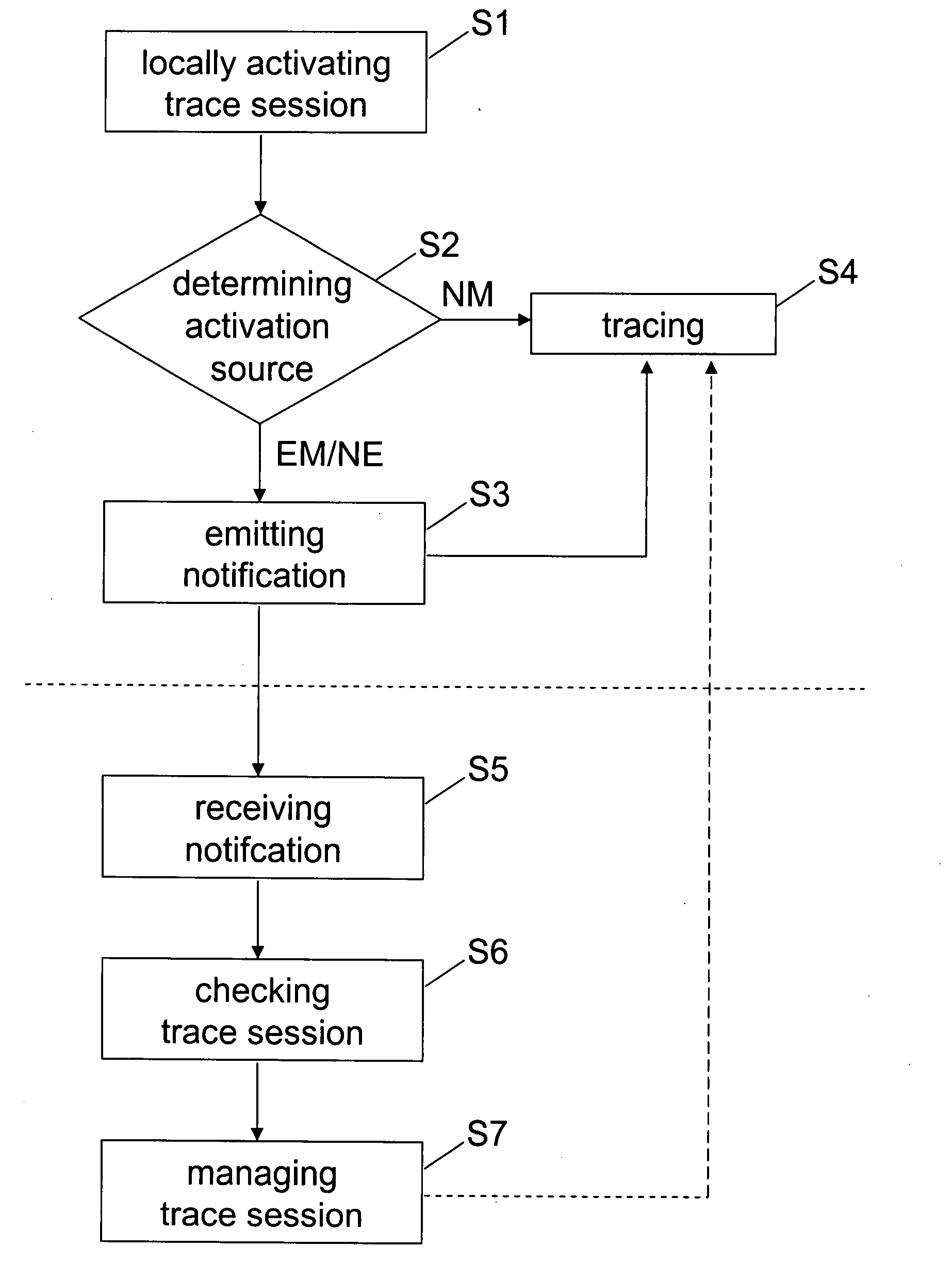
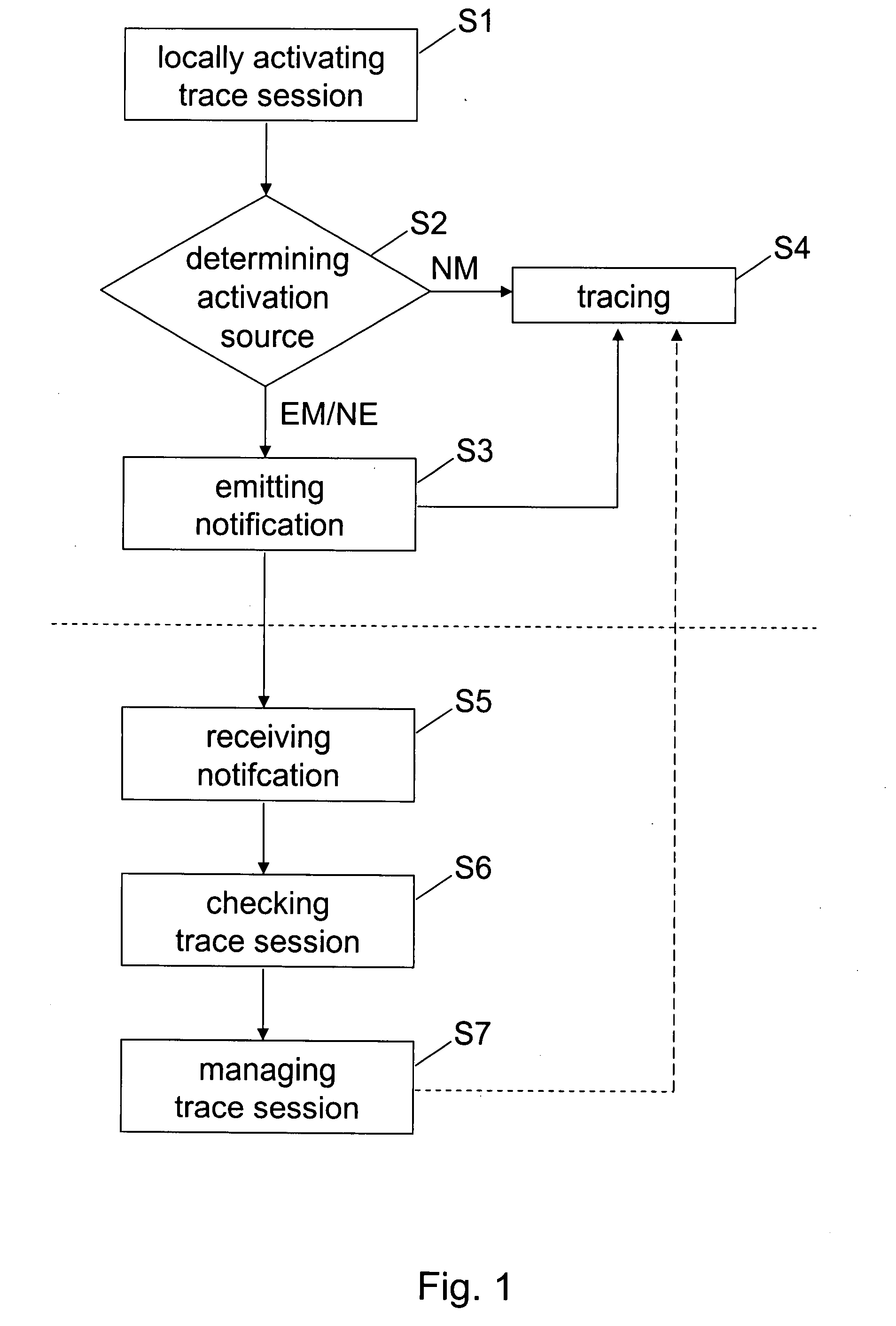
[0085]FIG. 1 shows a flow chart of a method according to an embodiment of the present invention. This method relates to a communication network including a network managing entity, hereinafter referred to as network manager NM, and at least one subordinate network entity, hereinafter referred to as element manager or network element depending on the particular system context concerned.

[0086]In FIG. 1, the upper half of the method flow above the broken line relates to an operation method of the above-mentioned subordina...


PUM


Abstract

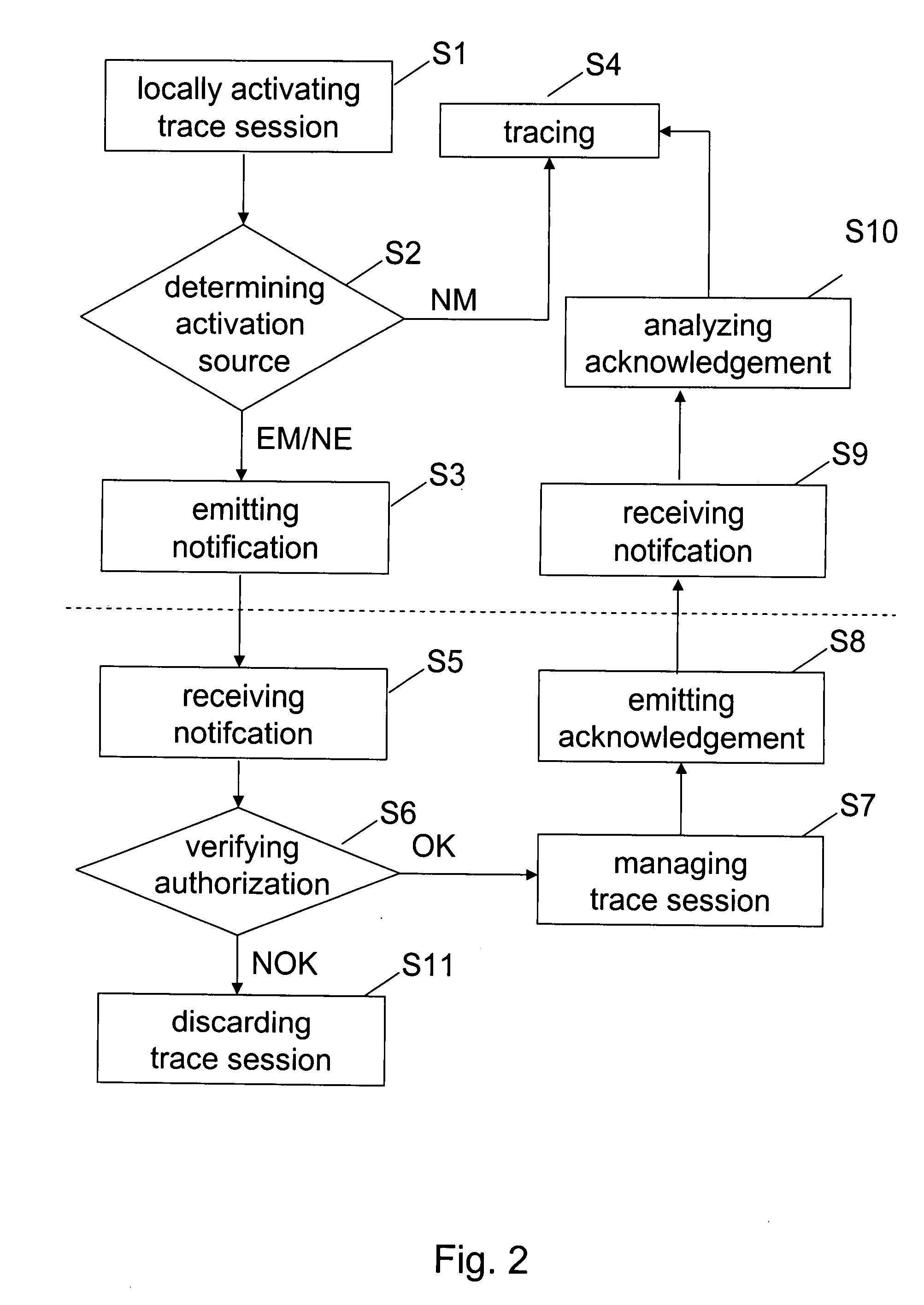
Automated central trace management in a communication network including a network managing entity and at least one subordinate network entity, comprising the steps of activating a trace session locally at the at least one subordinate network entity and emitting a notification of said activated trace session from the at least one subordinate network entity to the network managing entity.

Description

REFERENCE TO RELATED APPLICATIONS [0001]This application claims priority of U.S. Provisional Patent Application Ser. No. 60 / 784,755, filed on Mar. 23, 2006, the contents of which are hereby incorporated by reference.FIELD OF THE INVENTION [0002]The present invention relates to trace management in communication networks. In particular, the present invention relates to an automated central trace management for local trace activation in the network.BACKGROUND OF THE INVENTION [0003]In the field of network management and particularly communication network management, there is known the concept of tracing. To, this end, traces for every object to be traced are established in the network, which may for example be a second generation network such as GSM (Global System for Mobile Communication) or a third generation network such as UMTS (Universal Mobile Telecommunication System) or CDMA (Code Division Multiple Access), or any intermediary network such as GPRS (General Packet Radio Service)...

Claims


Application Information

Patent Timeline
Patent Type & Authority Applications(United States)
IPC IPC(8): G06F9/44
CPCH04W24/08H04L41/044
Inventor SUONVIERI, JUKKAGRAHAM, MERVYNBODOG, GYULAYU, YIN
Owner NOKIA CORP
Learn More