Micromachined fluidic device and method for making same

a fluidic device and micromachine technology, applied in the field of micromachine, can solve the problems of degrading the compression ratio achieved by the micropump, micropump not providing its own self-priming, and complex structure of the micropump, so as to achieve reliable and minimize dead volumes

Inactive Publication Date: 2007-12-25
DEBIOTECH SA
View PDF11 Cites 41 Cited by
  • Summary
  • Abstract
  • Description
  • Claims
  • Application Information

AI Technical Summary

Benefits of technology

[0008]An object of the present invention is to provide a fluid-flow device, e.g. a member for controlling liquid inlet or a member for detecting liquid pressure or a micropump, capable of being manufactured in simplified manner and constituting a fluid-flow device that is made reliable in its operation by minimizing dead volumes.
[0023]The use of this type of stack makes it possible to obtain a fluid-flow device presenting thicknesses that are constant and under strict control, while nevertheless implementing a method of manufacture that is simple.
[0029]In a first aspect of the fluid-flow device of the invention, there is provided a liquid inlet control member forming a non-return check valve, the member comprising a stack covered in a closure wafer, said stack comprising a support wafer, preferably made of silicon, a layer of insulating material, preferably made of silicon oxide, covering at least part of said support wafer, and a layer of single-crystal or polycrystalline silicon covering said layer of insulating material and covered by said closure wafer, said closure wafer and / or said silicon layer being machined so as to define a cavity between said closure wafer and said silicon layer, said cavity being designed to be filled with liquid and presenting at least one gap (or clearance hole) machined in the entire thickness of the silicon layer, said support wafer having at least one liquid inlet duct passing right through it and situated at least in register with (facing) said cavity, and said layer of insulating material having at least one zone entirely free of material extending at least in line with said duct and said gap so as to co-operate with said cavity to define a moving member in said silicon layer to form a flap for said valve, a portion of said silicon layer surrounding said moving member presenting elasticity making it possible in the event of a difference in liquid pressure between said liquid inlet duct and said cavity to allow said moving member to move reversibly towards said support wafer.
[0037]Thus, contrary to prior art fluid-flow devices and micropumps for which it is necessary to perform machining throughout the thickness of a silicon wafer that is to form the intermediate wafer between two wafers of glass, the present invention proposes using a stack in which the initial thicknesses of the three components (support wafer, layer of insulating material, and silicon layer) serve firstly to ensure that the various portions of the fluid-flow device are of well-controlled thickness, and secondly that the dead volumes are very considerably reduced compared with the prior art.

Problems solved by technology

Nevertheless, such a micropump does not provide its own self-priming since it presents large dead volumes, these volumes contributing to degrading the compression ratio achieved by the micropump.
Nevertheless, such a micropump is complex in structure, difficult to manufacture, and still has dead volumes that are large.

Method used


Image

  • Micromachined fluidic device and method for making same
  • Micromachined fluidic device and method for making same
  • Micromachined fluidic device and method for making same

Examples


second embodiment

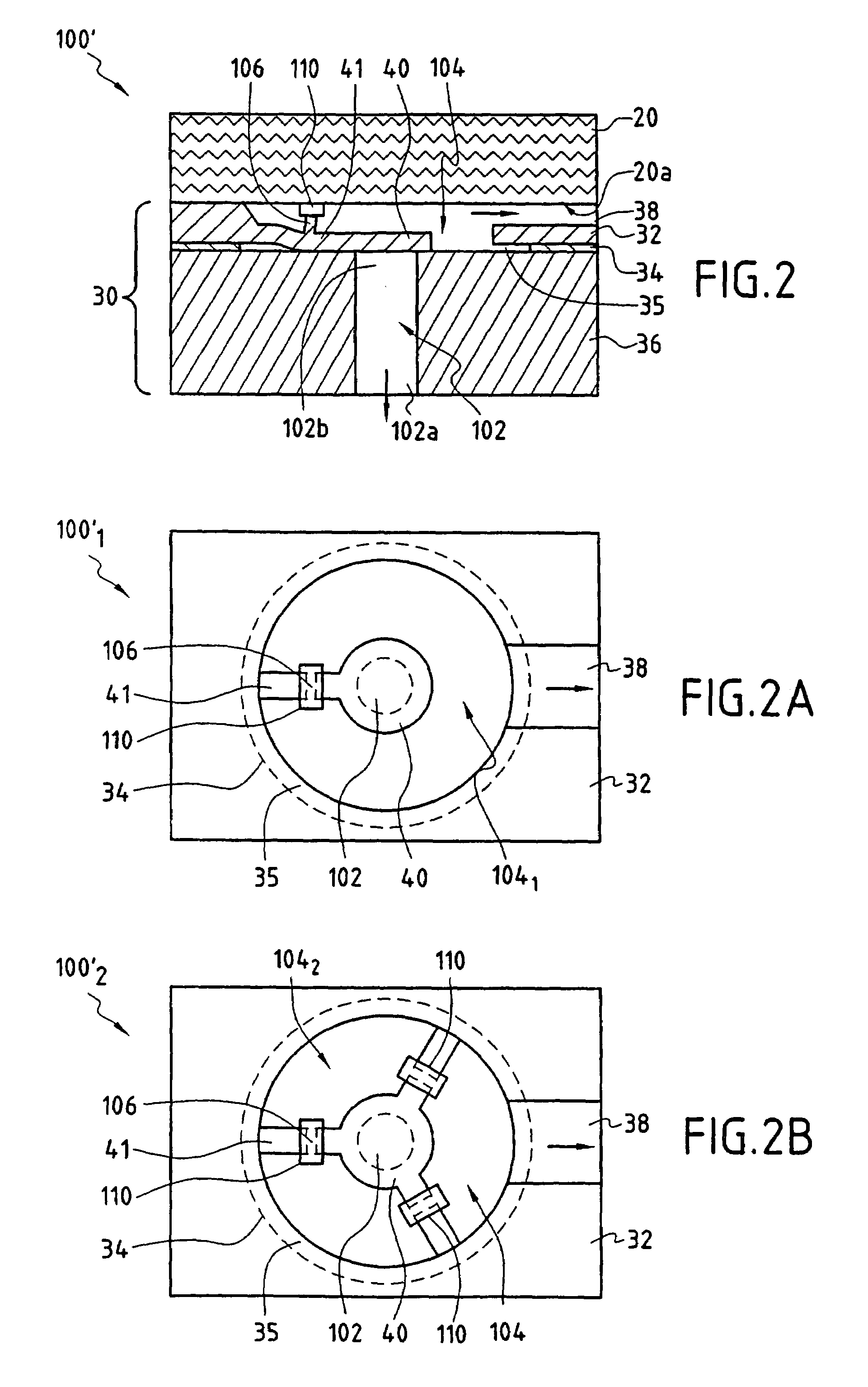
[0079]In a second embodiment shown in FIGS. 2, 2A, and 2B, it is also possible to establish prestress placing the liquid inlet control member 100′ in its closed position when the moving member 40 is in its rest position.

[0080]For this purpose, an isolated portion 106 of the moving member 40, situated in the middle of the arm 41, is of a thickness that is equal to the initial thickness of the silicon layer 32. This portion 106 lies in register with an element 110 situated on the face 20a of the closure wafer 20 facing towards the stack, or on the free face of said portion 106.

[0081]The element 110 is preferably taken from a layer of titanium deposited on the above-specified face 20a of the closure wafer 20. This element 110 pushes the isolated portion 106 downwards and forces the moving member 40 into its closed position which then corresponds to its rest position. Nevertheless, the elasticity of the moving member 40 remains sufficient to enable it to be opened.

[0082]Thus, the portio...

third embodiment

[0095]Like in the liquid inlet control member as shown in FIGS. 3 and 3A, and likewise for the purpose of offsetting the body and the seat of the valve between the second closure wafer 20′ and the silicon support wafer, a moving portion 361 is made throughout the thickness of the support wafer 36 of the liquid inlet control member 100′″, in register with and in line with said cavity 38 and said moving member 40.

[0096]This moving portion 361 is annular (see FIGS. 4 and 4A) and it is initially defined by a first annular volume 102′″a that has no material and that has been machined throughout the thickness of the support wafer 36 in register with said zone 35 that is completely free from material in the layer of insulating material 34 and said cavity 38. Thus, the first annular volume 102′″a separates said moving portion 361 from the remainder of the support wafer 36.

[0097]This annular moving portion 361 is subsequently likewise defined by a second cylindrical volume 102′″ which is fre...

embodiment 300

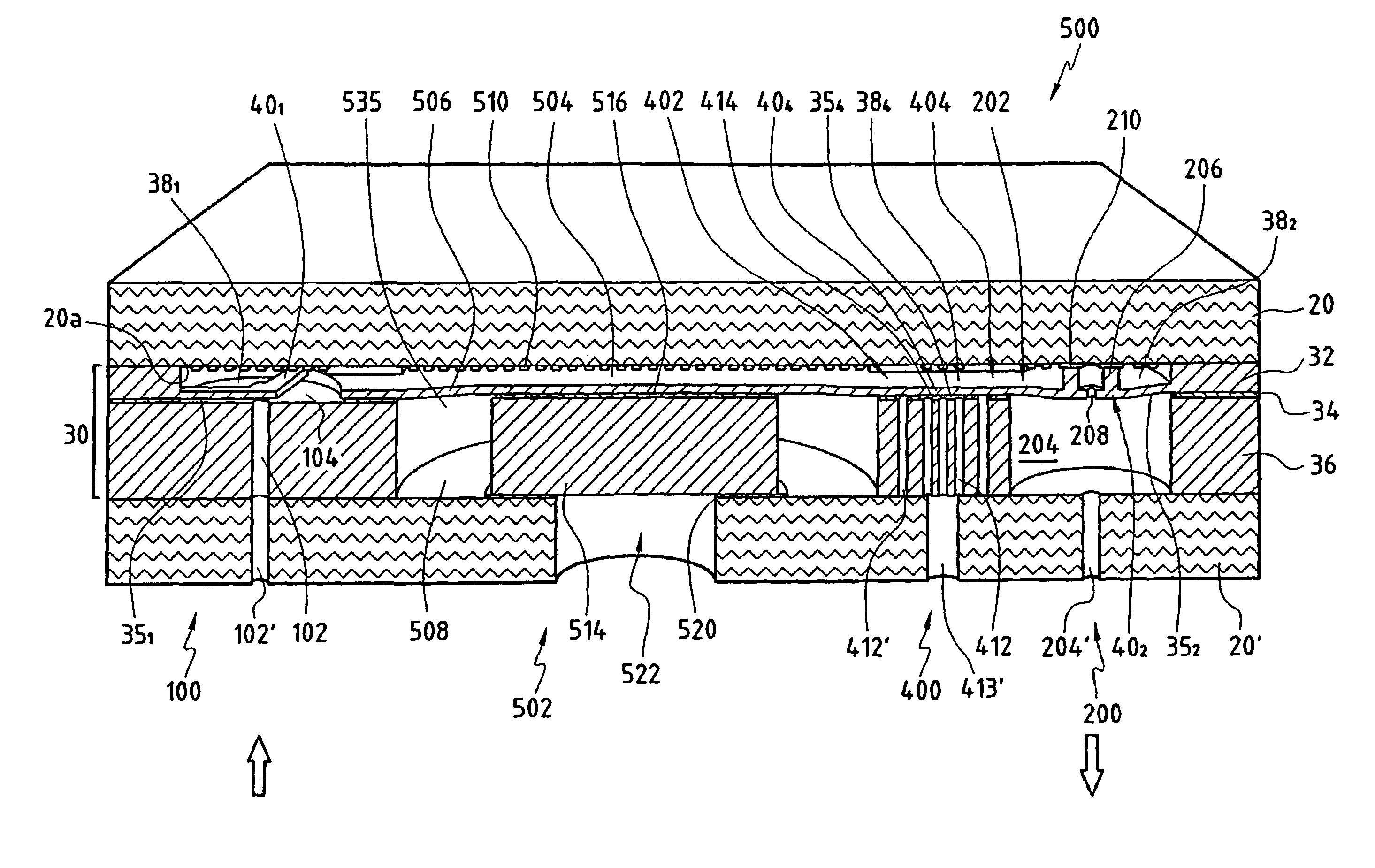
[0194]The liquid outlet control member 200 shown on a larger scale in FIG. 17, and its variant embodiment 300 shown in FIG. 18 are made using the same elements as the member 100 of FIG. 1.

[0195]As can be seen in FIG. 17, the liquid outlet control member 200 presents a liquid inlet 202 in the cavity 382 and a liquid outlet duct 204 machined through the entire thickness of the silicon support stack 36 in register with the cavity 38.

[0196]The zone 352 of the silicon oxide layer 34 that is free from material is located at least in line with the liquid outlet duct 204 and extends slightly beyond it all around said duct 204.

[0197]When making the cavity 38 by machining the silicon layer 32, the moving member 40 is formed with a fraction 206 extending over substantially the entire initial thickness of the silicon layer 32 and presenting a closed outline, preferably an annular outline. This fraction 206 extends from a first end 206a facing the zone 352 of the layer of insulating material 34 ...


PUM

PropertyMeasurementUnit
thicknessaaaaaaaaaa
thicknessaaaaaaaaaa
thicknessaaaaaaaaaa

Abstract

The fluid-flow device (100) of the invention comprises a stack (30) covered by a closure wafer (20), said stack (30) comprising a support wafer (36), a layer of insulating material (34), and a silicon layer (32). The closure wafer (20) and / or said silicon layer (32) are machined so as to define a cavity (38) between said closure wafer (20) and said silicon layer (32), said support wafer (36) has at least one duct (102) passing right through it, said layer of insulating material (34) presenting at least one zone (35) that is entirely free of material placed at least in line with said duct (102) so as to co-operate with said cavity (38) to define a moving member (40) in said silicon layer (32), the moving member being suitable under the pressure of liquid in said cavity (38) for reversibly moving towards said support wafer (36) until contact is made between said moving member (40) and said support wafer (36).

Description

RELATED APPLICATIONS[0001]This application is a divisional application of U.S. patent application Ser. No. 10 / 296,466 filed Mar. 31, 2003 now U.S. Pat. No. 7,005,078, which is a 35 USC 371 national stage application of PCT / EP01 / 07032 filed on 25 May 2001, which claims priority from France application FR 0006669 filed 25 May 2000.FIELD OF THE INVENTION[0002]The invention relates to a fluid-flow device and to its method of manufacture. The invention also relates to particular forms of fluid-flow device constituting a member for controlling liquid inlet, e.g. forming a non-return check valve, or a member for detecting liquid pressure.[0003]The present invention also relates to a micropump constituting a fluid-flow device, and particularly but not exclusively forming a micropump for medical use for delivering a controlled quantity of a liquid medicine on a regular basis.BACKGROUND OF THE INVENTION[0004]The manufacture of such fluid-flow devices, and in particular such micropumps is base...

Claims


Application Information

Patent Timeline
Patent Type & Authority Patents(United States)
IPC IPC(8): F04B17/00A61M1/00G01L9/00A61M37/00B81B3/00B81C1/00B81C3/00F04B9/00F04B43/02F04B43/04F16K15/14
CPCF04B43/043A61M5/14244
Inventor VAN LINTEL, HARALD T.MAILLEFER, DIDIERGAMPER, STEPHAN
Owner DEBIOTECH SA
Why Eureka
Try Eureka