Method of obtaining a sliding distance distribution of a dresser on a polishing member, method of obtaining a sliding vector distribution of a dresser on a polishing member, and polishing apparatus

a technology of sliding distance distribution and polishing member, which is applied in the direction of metal-working apparatus, manufacturing tools, and abrasive surface conditioning devices, etc., can solve the problems of lowering the polishing rate, polishing failure, and variation of the polishing rate on the polished surface of the workpiece, so as to achieve the effect of more accurate polishing

Active Publication Date: 2015-08-18
EBARA CORP
View PDF6 Cites 16 Cited by
  • Summary
  • Abstract
  • Description
  • Claims
  • Application Information

AI Technical Summary

Benefits of technology

[0014]Furthermore, a second object of the present invention is to provide a method of producing a novel index for evaluating the dressing of the polishing member.
[0042]According to the third aspect and the fourth aspect of the present invention, the sliding vector distribution of the dresser is obtained as the index for evaluating the dressing of the polishing member. This sliding vector represents not only the sliding distance of the dresser but also the sliding direction of the dresser. This sliding direction has an influence on a manner in which the dresser forms lines (scratches) on the polishing surface of the polishing member. Such lines (scratches) are considered to have an influence on a flow of a polishing liquid on the polishing member, a time during which the polishing liquid is present on the polishing member, and the like. Therefore, a dressing evaluation of the polishing member can be performed more accurately from the sliding vector distribution obtained.

Problems solved by technology

However, continuous polishing operations for the workpieces with use of the polishing member can crush the fine irregularities on the surface of the polishing member, thus causing a lowered polishing rate.
Therefore, if dressing is not performed appropriately, unwanted undulation is formed on the surface of the polishing member, causing a variation in a polishing rate within the polished surface of the workpiece.
Such a variation in the polishing rate can be a possible cause of polishing failure.
However, obtaining the profile of the polishing member by way of the actual measurement is a time-consuming operation and increases costs.

Method used


Image

  • Method of obtaining a sliding distance distribution of a dresser on a polishing member, method of obtaining a sliding vector distribution of a dresser on a polishing member, and polishing apparatus
  • Method of obtaining a sliding distance distribution of a dresser on a polishing member, method of obtaining a sliding vector distribution of a dresser on a polishing member, and polishing apparatus
  • Method of obtaining a sliding distance distribution of a dresser on a polishing member, method of obtaining a sliding vector distribution of a dresser on a polishing member, and polishing apparatus

Examples


Embodiment Construction

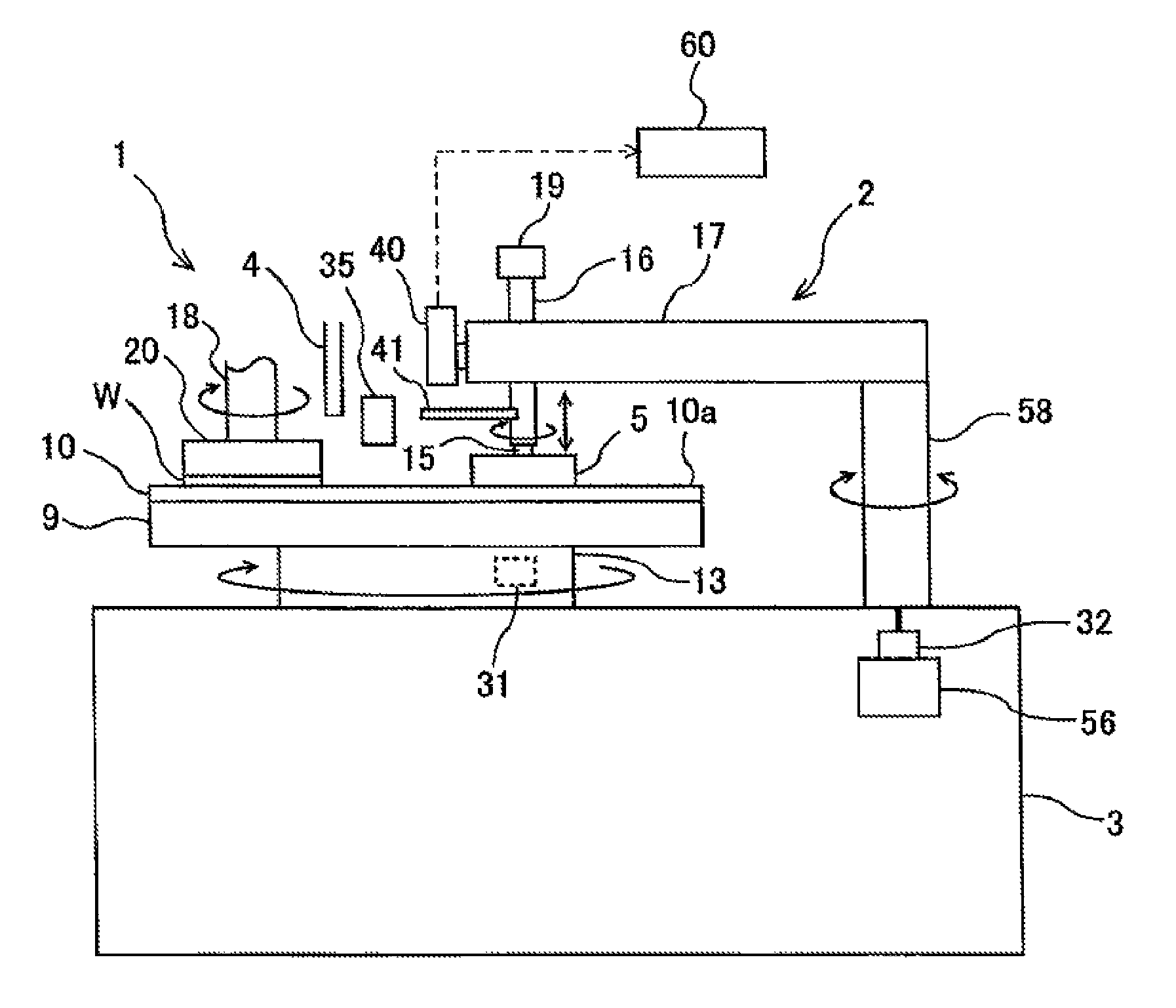
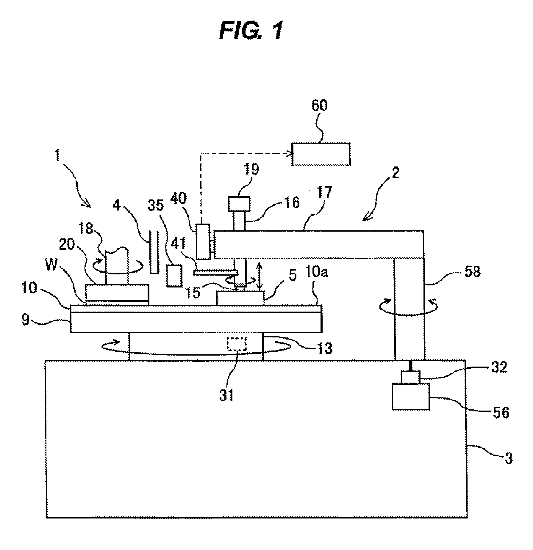
[0064]Embodiments according to the present invention will be explained with reference to the drawings. FIG. 1 is a schematic view showing a polishing apparatus for polishing a substrate, such as a wafer. As shown in FIG. 1, the polishing apparatus includes a polishing table 9 configured to hold a polishing pad (a polishing member) 10, a polishing unit 1 configured to polish a wafer W, a polishing liquid supply nozzle 4 configured to supply a polishing liquid onto the polishing pad 10, and a dressing unit 2 configured to dress (or condition) the polishing pad 10 which is used to polish the wafer W. The polishing unit 1 and the dressing unit 2 are provided on a base 3.

[0065]The polishing unit 1 includes a top ring (or a substrate holder) 20 coupled to a lower end of a top ring shaft 18. The top ring 20 is constructed so as to hold the wafer W on its lower surface by vacuum suction. The top ring shaft 18 is rotated by a motor (not shown in the drawing), and the top ring 20 and the wafe...


PUM


Abstract

The method includes: calculating an increment of a sliding distance of a dresser by multiplying a relative speed between the dresser and a polishing member by a contact time between them; correcting the increment of the sliding distance by multiplying the calculated increment of the sliding distance by at least one correction coefficient; calculating the sliding distance by repeatedly adding the corrected increment of the sliding distance to the sliding distance according to elapse of time; and producing the sliding-distance distribution of the dresser from the obtained sliding distance and a position of a sliding-distance calculation point. The at least one correction coefficient includes an unevenness correction coefficient provided for the sliding-distance calculation point. The unevenness correction coefficient is a correction coefficient that allows a profile of the polishing member to reflect a difference between an amount of scraped material of the polishing member in its raised portion and an amount of scraped material of the polishing member in its recess portion.

Description

CROSS REFERENCE TO RELATED APPLICATION[0001]This document claims priority to Japanese Patent Application Number 2013-033660 filed Feb. 22, 2013, the entire contents of which are hereby incorporated by reference.BACKGROUND OF THE INVENTION[0002]1. Field of the Invention[0003]The present invention relates to a method of obtaining a profile of a polishing member used in a polishing apparatus which polishes a surface of a workpiece, such as a wafer, and more particularly relates to a method of obtaining a sliding-distance distribution of a dresser on the polishing member by a simulation of a dressing operation.[0004]The present invention further relates to a method of obtaining a sliding vector distribution of a dresser which can be used for an evaluation of a dressing operation of a polishing member.[0005]Furthermore, the present invention relates to a polishing apparatus which can perform the above-mentioned methods.[0006]2. Description of the Related Art[0007]As a more highly integra...

Claims


Application Information

Patent Timeline
Patent Type & Authority Patents(United States)
IPC IPC(8): B24B53/017B24B53/00B24B53/02
CPCB24B53/005B24B53/017B24B53/02B24B53/12
Inventor SHIMANO, TAKAHIROTANIKAWA, MUTSUMIMATSUO, HISANORIYAMAGUCHI, KUNIAKIWATANABE, KATSUHIDE
Owner EBARA CORP
Why Eureka
Try Eureka