
Light-signaling glazing for a vehicle

a technology for signaling lights and vehicles, applied in fixed installations, lighting and heating equipment, instruments, etc., can solve problems such as increased production costs, serious road safety problems, and insufficiently satisfactory signaling lights

Active Publication Date: 2015-08-18
SAINT-GOBAIN GLASS FRANCE
View PDF15 Cites 2 Cited by
  • Summary
  • Abstract
  • Description
  • Claims
  • Application Information

AI Technical Summary

Benefits of technology

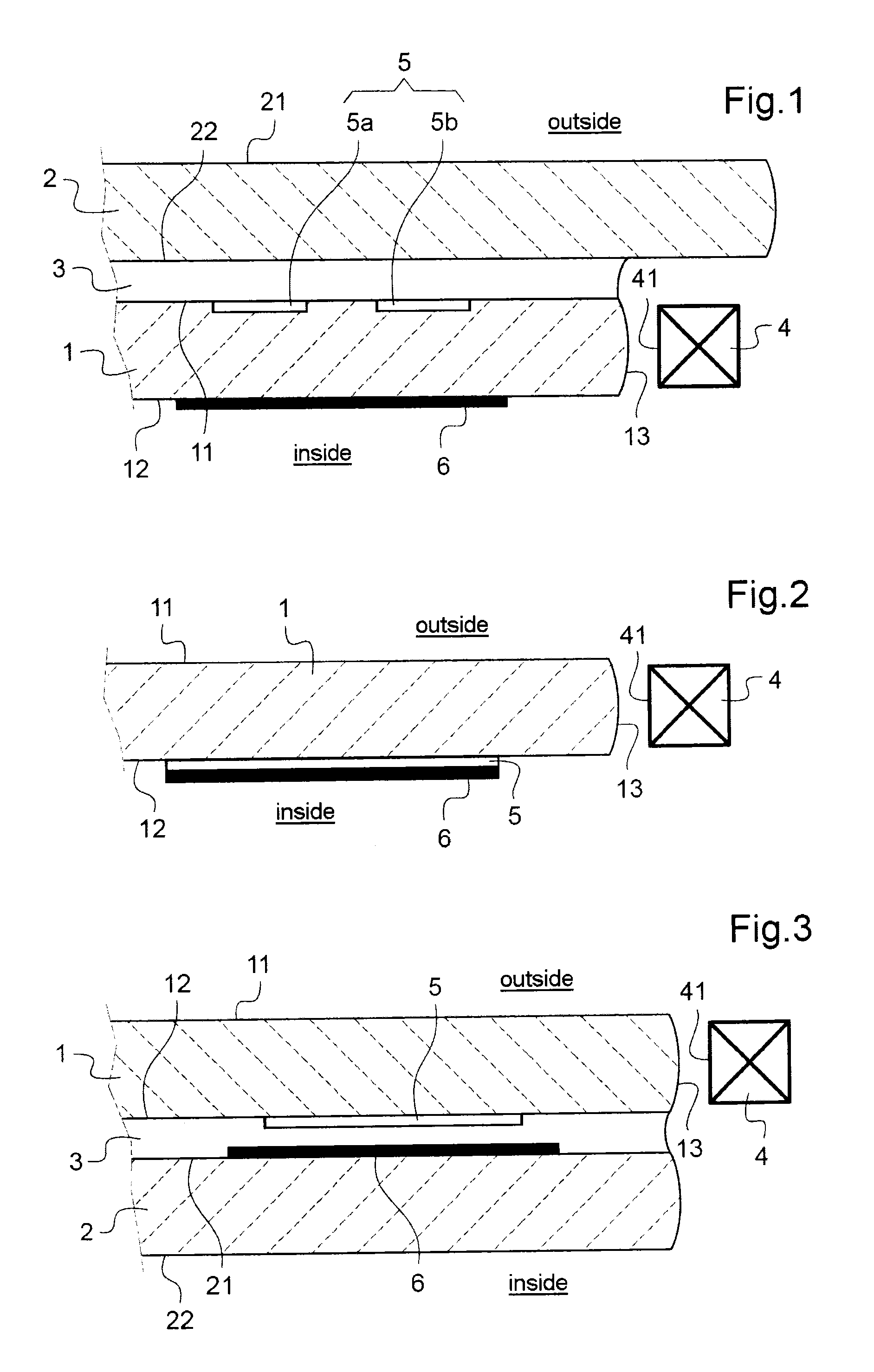
This patent describes a new type of illuminated signaling glazing unit for vehicles that is simple and low-cost to create. The unit is designed to achieve better illumination efficiency and aesthetic appeal. The invention provides two main variants: one where the illuminated sheet is in contact with the outside air, and another where the sheet is in contact with the passenger compartment air. The second variant results in a higher risk of visible scratches or dirt on the first sheet when it is illuminated, but offers better illumination efficiency. In a second embodiment, the means for extraction and rendering opaque are on the opposite main faces of the sheet, which reduces the effectiveness of masking the light. This embodiment also benefits from the use of a reflecting layer to improve illumination efficiency.

Problems solved by technology

Such a doubling up of the signaling lights involves one or more additional components to be managed in the production line and, as a result, increases the costs of production.
Furthermore, these additional, “displaced”, signaling lights are not always totally satisfactory from an aesthetic point of view.
Such an integration of additional light sources, which could be flashing, into the windows of a car poses however serious problems of road safety.
If light were emitted by windows toward the inside of the vehicle, there is a risk that it could, by transparency, also be visible on the outside of the latter.
It will also be understood that the visibility, by the driver, of the direction indicator lights of his own car could be very distracting in certain situations, notably while driving at night or when this light is reflected on glazing units or other reflecting surfaces inside of the vehicle.

Method used


Image

  • Light-signaling glazing for a vehicle
  • Light-signaling glazing for a vehicle
  • Light-signaling glazing for a vehicle

Examples


Embodiment Construction

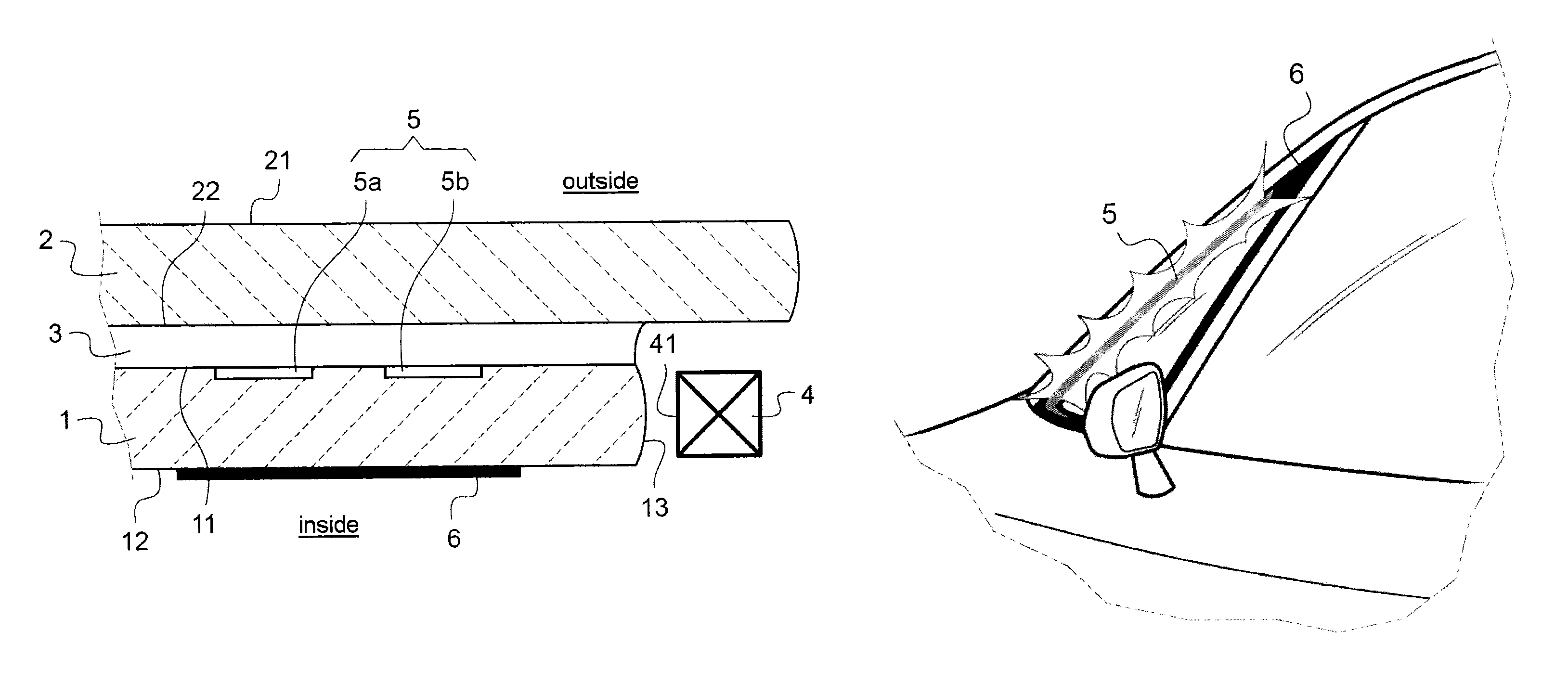
[0068]More particularly, FIG. 1 shows the edge of a laminated glazing unit as a cross-sectional view. A second sheet 2, in contact via its first main surface 21 with the outside air, is bonded by means of a sheet separating interface 3 to a first sheet 1, illuminated by its edge face 13. The sheet separating interface is in adhesive contact with the second main face 22 of the second sheet and with the first main face 11 of the first sheet. The second main face 12 of the first sheet 1 is in contact with the inside air of the vehicle. A light-emitting diode (LED) 4 is positioned near to the edge face 13 of the first sheet 1, its emission face 41 being opposite this edge face. The means for extraction of the light 5 is here made up of two regions 5a, 5b etched into the surface of the first main face 11 of the first sheet 1. The opaque layer 6, an enamel applied onto the second main face 12 of the first sheet, has a much greater extent than the two etched regions 5a, 5b and covers an ar...


PUM

PropertyMeasurementUnit
Fractionaaaaaaaaaa
Fractionaaaaaaaaaa
Fractionaaaaaaaaaa

Abstract

An illuminated vehicle signaling glazing unit, including: a first transparent sheet made of mineral glass including a first main face configured to be directed toward outside the vehicle, a second main face configured to be directed toward inside the vehicle, and an edge face; one or more light sources, or light-emitting diodes, each including a light-emission face opposite the edge face, light emitted by the light sources being guided into the first sheet between the first and the second main faces thereof; a mechanism extracting light in at least one region of the first or second main faces of the first sheet or within a thickness of the first sheet; and an opaque layer formed from ink or from enamel, situated toward the inside of the vehicle with respect to the extraction mechanism and totally masking the extraction mechanism of the light to render it invisible from inside the vehicle.

Description

BACKGROUND[0001]The present invention relates to an illuminated signaling glazing unit for a vehicle, preferably for an automobile vehicle, comprising a system for illuminating via the edge face of the glazing unit and means for rendering opaque preventing the emission of the light toward the inside of the vehicle.[0002]In the field of automobile vehicles, doubling up certain signaling lights such as the rear lights, direction indicator lights, stop lights or reversing lights, with light sources that are synchronized with these signaling lights and have the same color as the latter is a known technique. These light sources may be placed on the vehicle body, on the wing mirror (indicator light flasher) or else inside the passenger compartment, generally near the rear window, as described for example in the application EP 1 234 752. In the glazing unit described in this document, light-emitting diodes (LEDs) are placed in a unit situated around the periphery of the glazing unit on the...

Claims


Application Information

Patent Timeline
IPC IPC(8): F21S8/10B60Q1/38B60Q1/26B60J1/10B32B17/10F21V8/00
CPCB32B17/10036B60J1/10B60Q1/268B60Q1/38B32B17/10541F21S48/20B32B17/10348G02B6/0073G02B6/0035G02B6/0068F21S43/14F21S43/50F21S43/30B60J1/08B60Q1/32B60Q1/34B32B17/10
Inventor MASSAULT, LAETICIAVERRAT-DEBAILLEUL, ADELEBAUERLE, PASCALMILHE POUTINGON, SOPHIE
Owner SAINT-GOBAIN GLASS FRANCE
Learn More