Phase-locked loop start up circuit

a start-up circuit and phase lock technology, applied in the field of circuits, can solve the problems of conventional pll circuits that have subtle problems that are difficult to overcome, circuits working at the ss corner failing to start oscillating,

Active Publication Date: 2015-08-18
TAIWAN SEMICON MFG CO LTD
View PDF8 Cites 17 Cited by
  • Summary
  • Abstract
  • Description
  • Claims
  • Application Information

AI Technical Summary

Problems solved by technology

An additional problem with the conventional PLL circuit is caused by process, voltage, and temperature (PVT) variations, which cause different PLL circuits, although having a same design, to work on different process corners, such as fast-fast (FF) corner, slow-slow (SS) corner, and the like.
Unfortunately, this may cause the circuits working at the SS corner to fail to start oscillating.
Per the foregoing discussion, the conventional PLL circuits have subtle problems that are difficult to overcome.

Method used


Image

  • Phase-locked loop start up circuit
  • Phase-locked loop start up circuit
  • Phase-locked loop start up circuit

Examples


Embodiment Construction

[0018]This description of the exemplary embodiments is intended to be read in connection with the accompanying drawings, which are to be considered part of the entire written description. Relative terms are used for convenience of description and do not require that the apparatus be constructed or operated in a particular orientation. Terms concerning electrical communications and the like, such as, “coupled” and “electrically coupled” or “electrically connected,” refer to a relationship wherein nodes communicate with one another either directly or indirectly through intervening structures or elements, unless described otherwise.

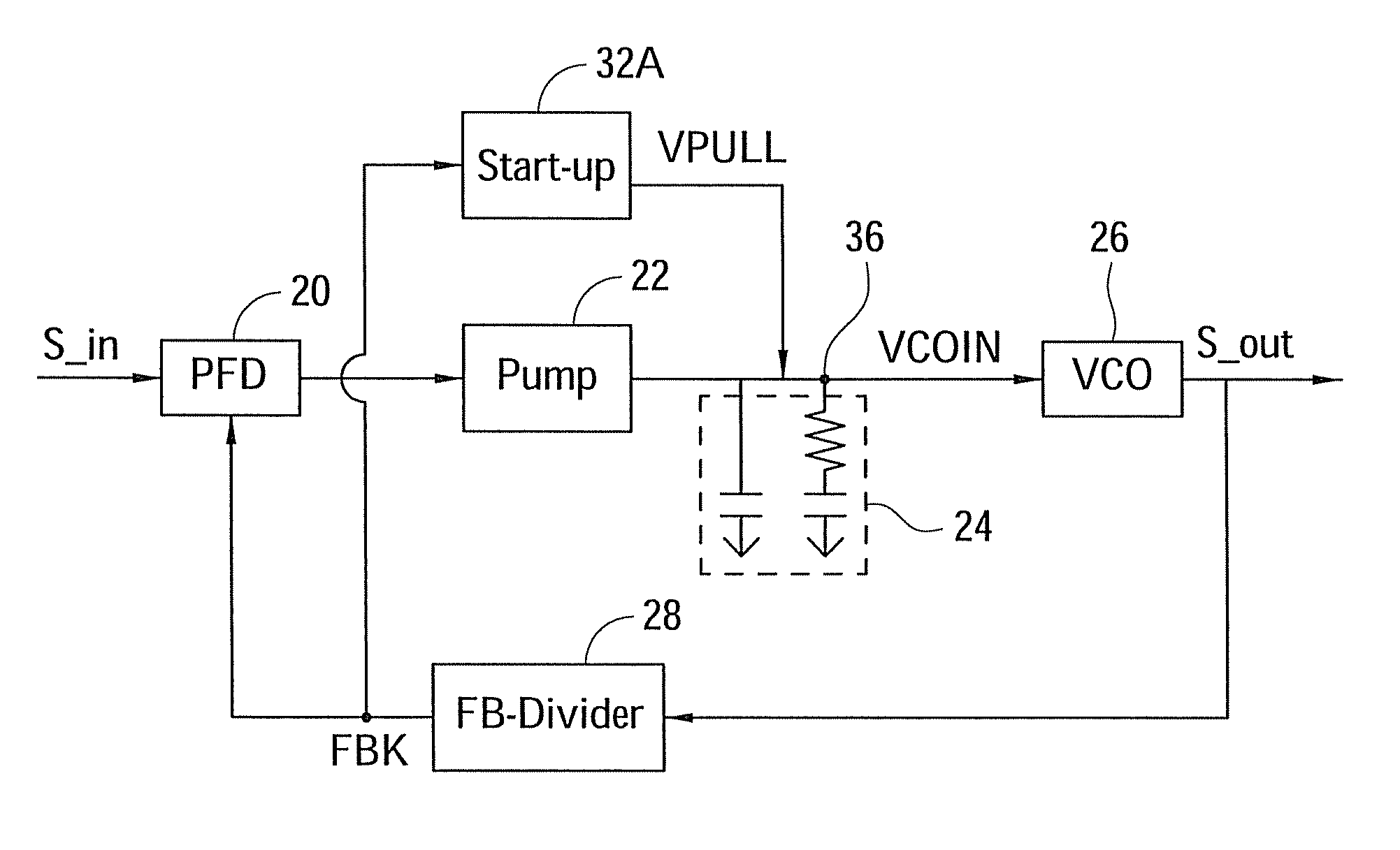
[0019]FIG. 3 illustrates an embodiment of a charge pumped phase-locked loop circuit according to an embodiment of the present invention. In the illustrated embodiment, the PLL circuit includes a phase frequency detector (PFD) 20, charge pump 22, low-pass loop filter 24, voltage-controlled oscillator (VCO) 26, a feedback (FB) divider 28, and a start-up circui...


PUM


Abstract

A phase-locked loop (PLL) circuit includes a voltage-controlled oscillator (VCO) having a VCO input for receiving a control voltage and a VCO output, a feedback loop between the VCO input and the VCO output, and a start-up circuit having a start-up circuit input and a start-up circuit output. The start-up circuit output is coupled to the VCO input and the start-up circuit input is coupled to the VCO output. The start-up circuit provides a voltage at its start-up circuit output during a start-up phase, which terminates after a predetermined number of feedback pulses are detected by the start-up circuit.

Description

FIELD OF THE INVENTION[0001]The present disclosure relates generally to circuits, and more particularly to phase-locked loop circuits utilizing start-up circuits.BACKGROUND OF THE INVENTION[0002]Phase-locked loop (PLL) circuits are widely used in integrated circuit designs, such as in the design of receivers. PLL circuits are basically closed-loop frequency control systems whose operation is based on the phase sensitive detection of the phase difference between an input signal and an output signal.[0003]FIG. 1 illustrates a conventional PLL circuit, which includes phase frequency detector (PFD) 20, charge pump 22, low-pass loop filter 24, voltage-controlled oscillator (VCO) 26, feedback (FB) divider 28, and start-up circuit 32. Input signal S_in having an input frequency F_in is input into the PLL circuit and an output signal S_out having an output frequency F_out is generated by the PLL.[0004]A schematic diagram of start-up circuit 32 is shown in FIG. 2. Start-up circuit 32 include...

Claims


Application Information

Patent Timeline
Patent Type & Authority Patents(United States)
IPC IPC(8): H03L7/00H03L7/10H03L7/06H03L3/00
CPCH03L3/00H03L7/101
Inventor CHEN, CHIEN-HUNGCHOU, MAO-HSUANTSAI, TSUNG-HSIEN
Owner TAIWAN SEMICON MFG CO LTD
Why Eureka
Try Eureka