Image capturing apparatus that controls performing of short-term and long-term exposures and corresponding read operations, and control method thereof

a technology of image capture and control, applied in the field of image capture apparatus, can solve the problems of deterioration of an s/n, image quality drop caused by shadow-detail loss and image quality drop, and achieve the effect of simplifying timing control

Inactive Publication Date: 2015-08-18
CANON KK
View PDF9 Cites 1 Cited by
  • Summary
  • Abstract
  • Description
  • Claims
  • Application Information

AI Technical Summary

Benefits of technology

[0017]The present invention realizes improvement of a rolling shutter operation required for dynamic range expansion processing, and a method which can attain both averaging of processing loads imposed on read operations of pixel signals and simplification of timing control.

Problems solved by technology

An image capturing apparatus using an image sensor such as a CMOS sensor suffers a problem that a dynamic range is normally insufficient upon capturing an image of an object including both a bright part and dark part.
For example, when an exposure time is controlled to be short in correspondence with a bright part, since a sufficient exposure time for a dark part cannot be assured, a shadow-detail loss and an image quality drop caused by deterioration of an S / N are generated.
Conversely, when an exposure time is controlled to be long in correspondence with a dark part, accumulated charge amounts of some photoelectric conversion elements reach a saturation level, thus generating a highlight-detail loss in which an object region having a given brightness or higher is set at a saturated luminance level.
Furthermore, when an exposure time ratio is 2:1, since a maximum exposure time of the short-term exposure is set to be half of one frame period, a wasteful time which does not contribute to exposure is generated.
Also, in the multi-exposure method, a time difference for one frame period is generated between the long-term exposure and short-term exposure.
As a result, in an image which has undergone the dynamic range expansion processing, the moving object may be blurred and false colors may be generated.
Such processing imposes a heavy load on a signal processing circuit.
Therefore, such method requires complicated timing control.

Method used


Image

  • Image capturing apparatus that controls performing of short-term and long-term exposures and corresponding read operations, and control method thereof
  • Image capturing apparatus that controls performing of short-term and long-term exposures and corresponding read operations, and control method thereof
  • Image capturing apparatus that controls performing of short-term and long-term exposures and corresponding read operations, and control method thereof

Examples


first embodiment

[0037]The first embodiment will explain an operation of an image sensor which is controlled to output signals of pixels of different exposure times at 2-line intervals so as to be used in dynamic range expansion processing (to be referred to as “HDR processing” hereinafter).

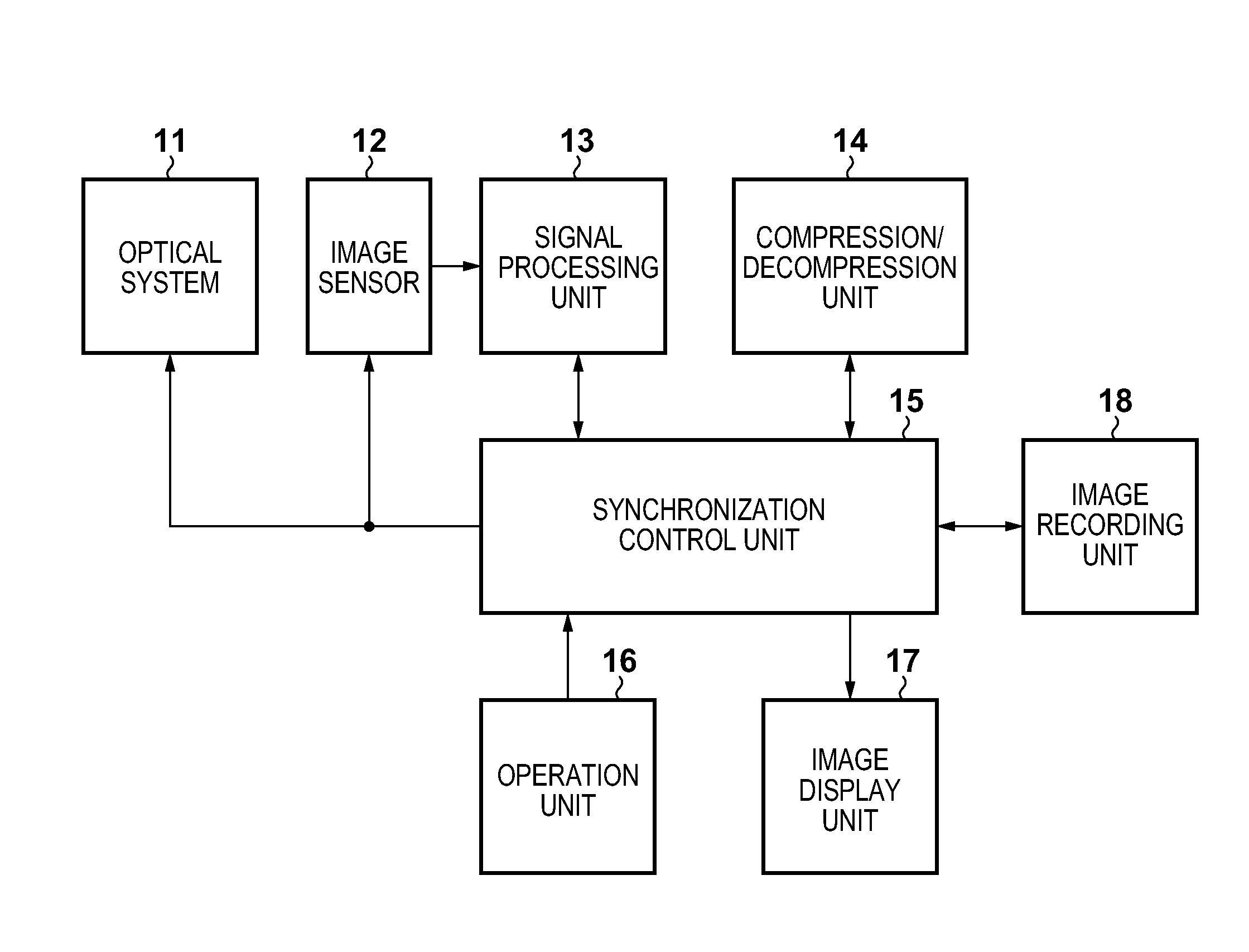
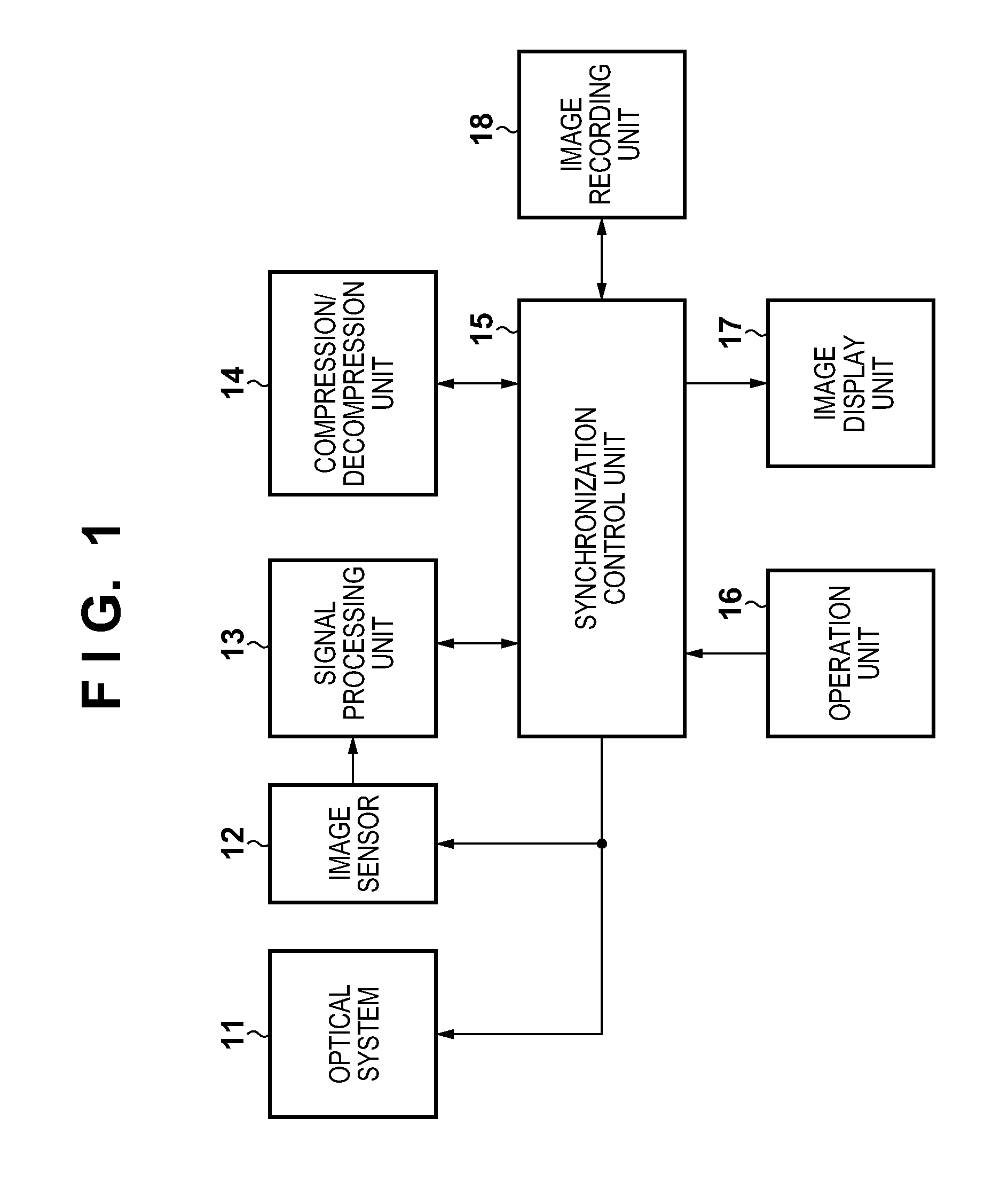
[0038]FIG. 1 is a block diagram showing the arrangement of an image capturing apparatus according to this embodiment. The image capturing apparatus of this embodiment is applicable to a digital still camera, digital video camera, and the like. The image capturing apparatus shown in FIG. 1 includes an optical system 11, image sensor 12, signal processing unit 13, compression / decompression unit 14, synchronization control unit 15, operation unit 16, image display unit 17, and image recording unit 18. The optical system 11 includes a lens required to focus light coming from an object onto the image sensor 12, a driving mechanism required to move the lens to attain a zoom operation and in-focus operation, a mechanica...

second embodiment

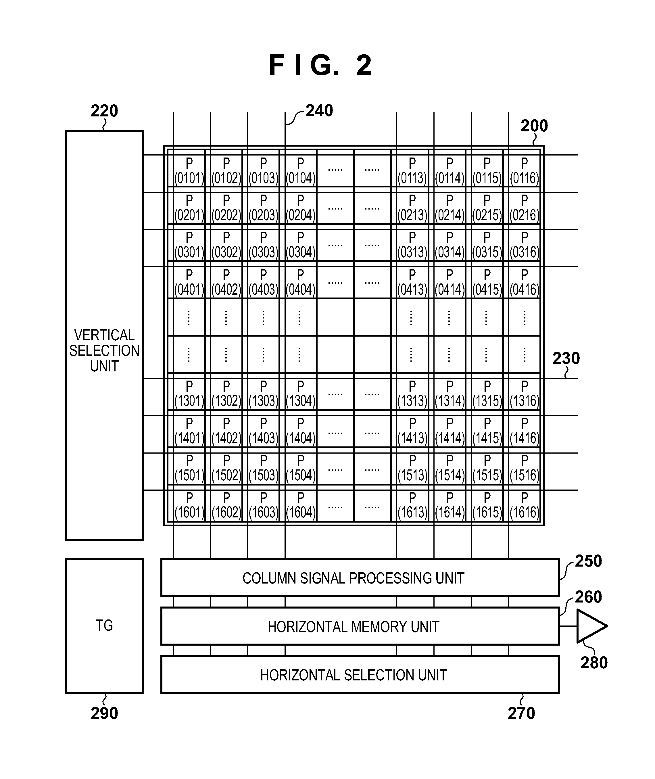
[0133]In the first embodiment, two frames, that is, a long-term exposure frame and short-term exposure frame are set to have different exposure times at 2-line intervals. In the second embodiment, by further adding a frame having a different exposure time, an image with a broader dynamic range is generated. A case will be described below wherein a middle-term exposure frame is set in addition to a long-term exposure frame and short-term exposure frame as frames having different exposure times at 2-line intervals. Note that in this embodiment, the basic arrangement and operation of an image capturing apparatus and those of an image sensor are the same as those in the first embodiment. Therefore, in this embodiment, FIGS. 1 and 2 will also be quoted, and the same reference numerals in FIGS. 5 and 6 to be described below denote the same elements as in FIGS. 3 and 4.

[0134]FIG. 5 is a timing chart showing control timings of an image sensor 12 according to this embodiment. In this embodim...

third embodiment

[0229]The third embodiment of the present invention will be described below with reference to FIGS. 1, 2, and 7 to 9. Note that in this embodiment, the basic arrangement and operation of an image capturing apparatus and those of an image sensor are the same as those in the first embodiment, and the following description will be given by quoting the figures and reference numerals.

[0230]In the first embodiment, two frames, that is, a long-term exposure frame and short-term exposure frame are set to have different exposure times at 2-line intervals to generate an image with a broad dynamic range. In this embodiment, a case will be described wherein a plurality of short-term exposure frames are set in a long-term exposure frame.

[0231]FIG. 7 is a timing chart showing control timings of long-term exposure lines and short-term exposure lines according to this embodiment. Referring to FIG. 7, VDL represents a vertical synchronizing signal (long-term vertical synchronizing signal) for a long...


PUM


Abstract

An image capturing apparatus is provided. A synchronizing signal generation unit generates a short-term vertical synchronizing signal VDS and a long-term vertical synchronizing signal VDL, one cycle of which is equal to N cycles of VDS. An exposure control unit performs short-term exposure and long-term exposure for the predetermined number of lines of an image sensor according to VDS and VDL. The exposure control unit starts a read operation of pixel signals for a long-term exposure line in synchronism with VDL, and starts a read operation of pixel signals for a short-term exposure line in synchronism with VDS, which does not overlap a read period Fr_L Readout of pixel signals of a long-term exposure line.

Description

BACKGROUND OF THE INVENTION[0001]1. Field of the Invention[0002]The present invention relates to an image capturing apparatus and control method thereof.[0003]2. Description of the Related Art[0004]As an image sensor used in an image capturing apparatus, a CCD (Charge Coupled Device) type image sensor (to be referred to as “CCD sensor” hereinafter) is generally adopted. However, in recent years, as image sensors are required to have a larger number of pixels, a CMOS (Complementary Metal Oxide Semiconductor) type image sensor (to be referred to as “CMOS sensor” hereinafter) has received a lot of attention.[0005]In an image sensor such as a CMOS sensor, photoelectric conversion elements of pixels perform photoelectric conversion for accumulating charges according to incident light amounts, and outputting electrical signal corresponding to the accumulated charges. Also, an image sensor such as a CMOS sensor has an electronic shutter function. The electronic shutter function starts expo...

Claims


Application Information

Patent Timeline
Patent Type & Authority Patents(United States)
IPC IPC(8): H04N5/235H04N5/353H04N5/374H04N5/355
CPCH04N5/3532H04N5/35509H04N5/35527H04N5/35581H04N5/374H04N25/531H04N25/571H04N25/575H04N25/589H04N25/76
Inventor YANAI, TOSHIKAZU
Owner CANON KK
Why Eureka
Try Eureka