
Parallel Interface Timing Control Device

A timing control and interface technology, applied in the field of communication, can solve problems such as complex interface control, complex timing control, and slow switching time, and achieve the effects of reducing physical pin resources, simplifying interface timing control, and reducing packaging area

Active Publication Date: 2018-06-26
SANECHIPS TECH CO LTD
View PDF2 Cites 0 Cited by
  • Summary
  • Abstract
  • Description
  • Claims
  • Application Information

AI Technical Summary

Problems solved by technology

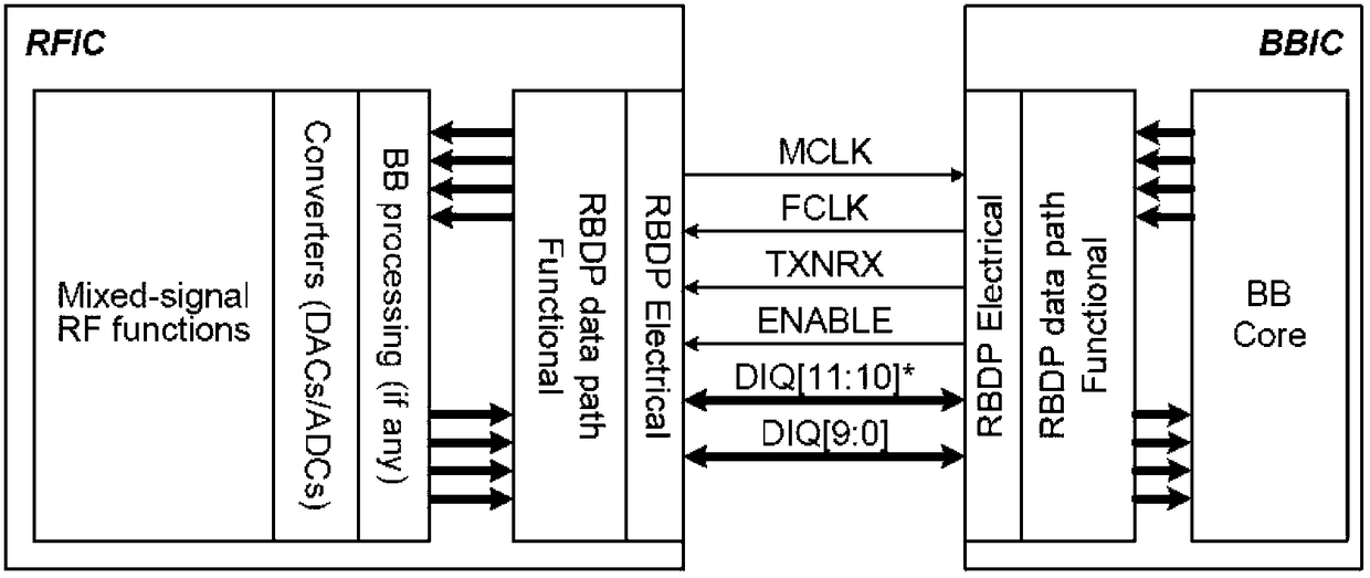
[0008] Moreover, when the terminal performs transceiver switching, the TXNRX signal and the FCLK clock have a strict timing constraint relationship, and the TXNRX signal and the enable signal also have a strict timing constraint relationship, and data transmission has a fixed delay compared to the enable pulse signal
These strictly constrain the transceiver switching control and data transmission timing together, which is very complicated in timing control, and the switching time will be relatively slow, which is contrary to the goal of fast transceiver switching required by the TDD system
[0009] In addition, the JESD207-RBDP interface only supports TDD data transmission. For Frequency Division Duplex (FDD)-LTE terminals, it is required to realize the simultaneous transmission of the first data. Obviously, the timing of this interface cannot meet the requirements.
[0010] Therefore, the parallel interface standard in the prior art mainly has the following defects: the interface control is complex, and it can only support the data transmission of the TDD system but cannot support the data transmission of the FDD system

Method used


Image

  • Parallel Interface Timing Control Device
  • Parallel Interface Timing Control Device
  • Parallel Interface Timing Control Device

Examples


Embodiment Construction

[0036] Hereinafter, the present invention will be described in detail with reference to the drawings and in conjunction with the embodiments. It should be noted that the embodiments in the application and the features in the embodiments can be combined with each other if there is no conflict.

[0037] Figure 4 It is a structural block diagram of a parallel interface timing control device according to an embodiment of the present invention, such as Figure 4 As shown, the device mainly includes:

[0038] The parallel interface timing control device provided by the present invention is located in an analog baseband (ABB) or a digital baseband (DBB), and mainly includes a control module 10, a channel multiplexing module 20, and a channel demultiplexing module 30. Among them, the control module 10 is used to receive control information from the system and status indication information from the peer baseband, and generate control sequence and status indication signals according to the ...


PUM


Abstract

The invention discloses a parallel interface sequential control device which is positioned at an analog baseband or digital baseband. The device comprises the following modules: a control module used for receiving control information from a system and status indication information from an opposite-end baseband and generating a control sequence and a status indication signal according to the control information and the status indication information, wherein the control sequence can control a channel multiplexing module to send data and control a channel demultiplexing module to receive data and the status indication signal indicates the data sending / receiving status; the channel multiplexing module used for sending first data through a two-channel to the opposite-end baseband according to the control sequence when the status indication signal indicates the sending status; and the channel demultiplexing module used for receiving second data from the opposite-end baseband through the two-channel according to the control sequence when the status indication signal indicates the receiving status. According to the invention, interface sequential control complexity is simplified, and power consumption is minimized.

Description

Technical field [0001] The invention relates to the field of communications, and in particular to a parallel interface timing control device. Background technique [0002] With the rapid development of mobile communication technology, from the first generation of analog communication to the second generation of digital mobile communication, to the third generation of broadband mobile communication and the fourth generation of Long Term Evolution (LTE) technology. In addition to the complete replacement of the first-generation analog technology, the second, third, and fourth-generation mobile communications will exist at the same time now and in the future, forming a long-term coexistence of multi-standard and multi-standard mobile communications. In this way, users' requirements for mobile terminals have also changed from traditional single-mode to multi-mode requirements. Under this demand, Global System for Mobile communication (GSM) single-mode multi-mode multiple standby, G...

Claims


Application Information

Patent Timeline
Patent Type & Authority Patents(China)
IPC IPC(8): H04L29/10
Inventor 张衡张怀福潘晓锋
Owner SANECHIPS TECH CO LTD
Learn More