Dual force plate apparatus

a technology of plate apparatus and plate plate, applied in the field of plate plate apparatus, can solve the problems of outperforming predecessors, current devices, and complex changes, and achieve the effect of being convenient to carry

Inactive Publication Date: 2015-08-25
I P SOLUTIONS LTD
View PDF13 Cites 1 Cited by
  • Summary
  • Abstract
  • Description
  • Claims
  • Application Information

AI Technical Summary

Benefits of technology

[0016]In a preferred embodiment, the second rigid rectangular frame is secured to the first rigid rectangular frame by one or more hinges so that the apparatus is selectively movable from a first extended position in which the first and second frames are substantially coplanar and relative lateral movement between the frames is prevented, and a second folded position. In this embodiment, the apparatus is readily portable.

Problems solved by technology

These have evolved in complexity as computers have evolved, and current devices outstrip their predecessors in ability to analyze the components of a golf swing or other repetitive sports move, although an optimum device has yet to be developed.
No memory of the swing is available, and swing to swing comparison is not possible.
Such plates can determine the proportion of total weight on each, but cannot provide data on center of gravity because the computer does not know the position of one in relation to the other.
The foot pads can also potentially slip apart during use.
Several of the devices, notably those of Heisler and Cromarty and another by Cecchin (U.S. Pat. No. 6,039,658), include two foot plates that measure total weight on each foot, but are unable to differentiate weights from different portions of the foot, such as the heel and toes or the inside versus the outside of the foot.
Nesbit and Mooney (U.S. Pat. No. 7,946,928) have cantilevered devices to measure heel and toe weights, but in each case the foot pads, like Bregman's, are separate and movable, so the center of gravity cannot be measured.
This also raises the possibility that the actual times when the feature events occur in the player's swing may not be exactly when predicted and measured by the pre-set timing parameters of the device.
In addition, a common disadvantage of the previous devices has been that they have been non-portable and connected to computers via bulky cables.
None has been capable of being taken outside for simulation in the yard or at an actual driving range or golf course.

Method used


Image

  • Dual force plate apparatus
  • Dual force plate apparatus
  • Dual force plate apparatus

Examples


Embodiment Construction

[0027]It is to be understood that the specific devices and processes illustrated in the attached drawings and described in the following description are simply exemplary embodiments of the inventive concepts defined in the appended claims. Hence, specific dimensions and other physical characteristics relating to the embodiments disclosed herein should not be considered as limiting, unless the claims expressly state otherwise.

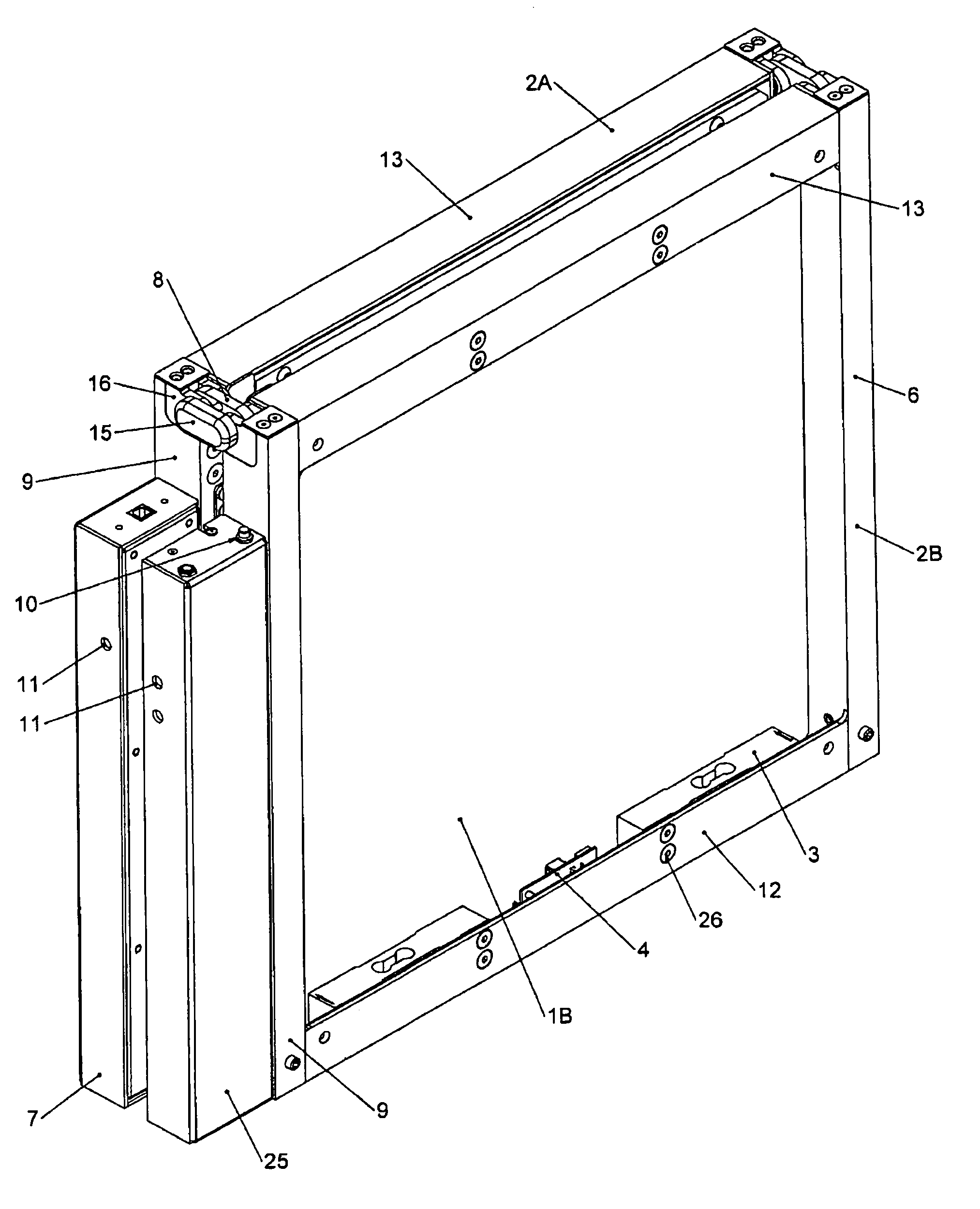
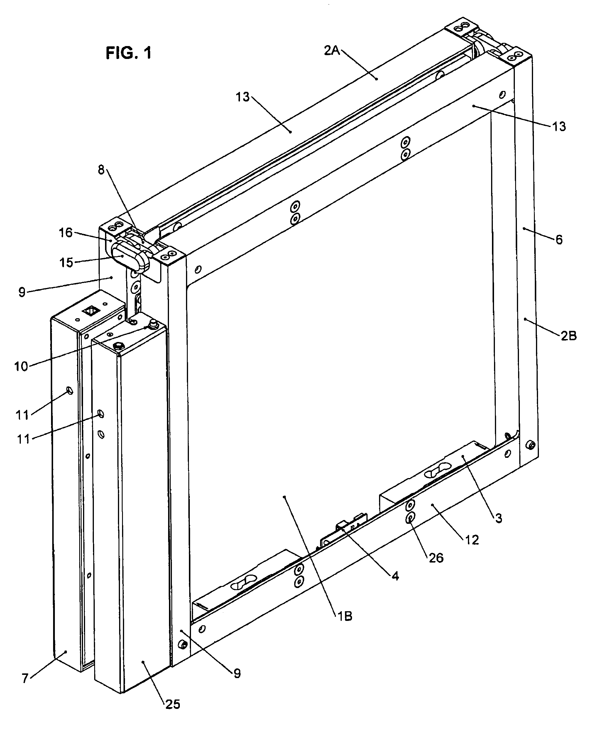
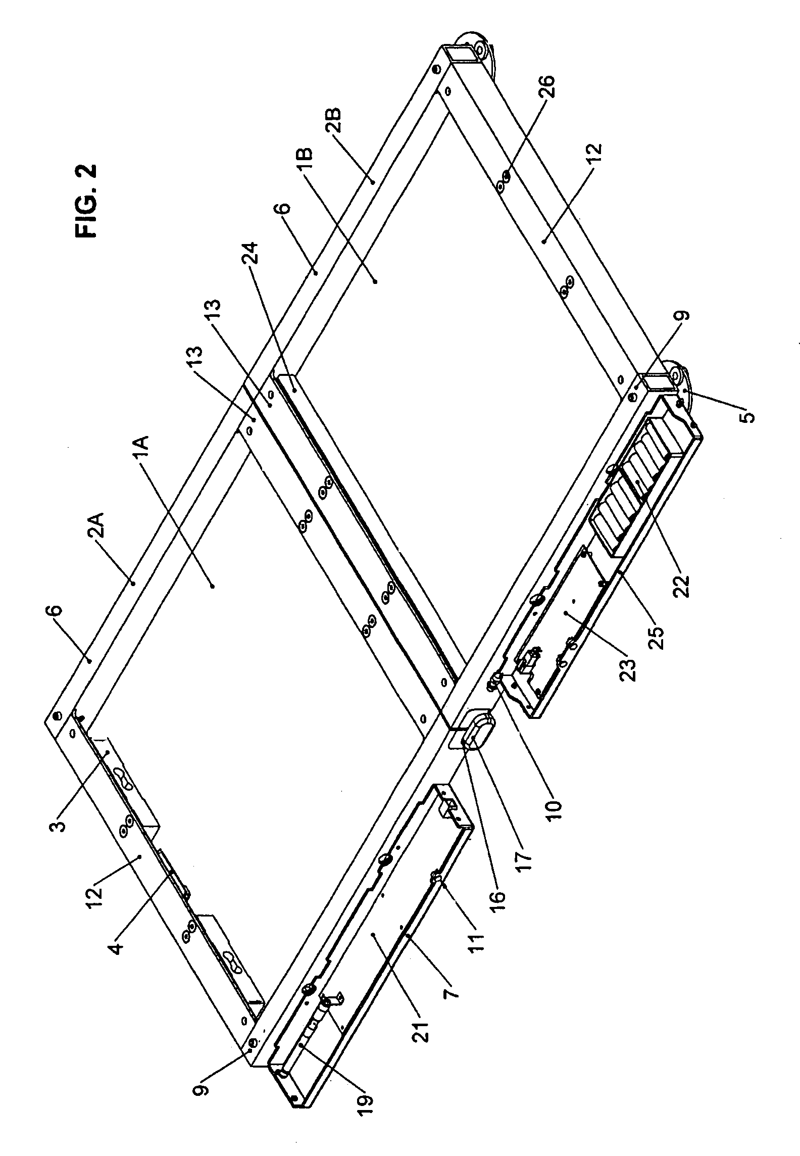
[0028]The apparatus of the invention is a golf or other sports action device for use outside, away from home, or wherever the user or player desires, that accurately and sensitively measures weight and forces on each foot, the heel and toe positions, and the positions of the inside and outside of each foot during a golf swing or similar activity by employing a chassis device with two independent but physically joined force plates and frames, each plate being mounted within its respective frame by at least four load cells. The portion of the frame about the first...


PUM


Abstract

An apparatus for analyzing a golf swing or other biomechanical movement includes first and second rectangular force plate mounted within a respective first and second rigid rectangular frame by means of at least one load cell proximate each corner of each rectangular force plate. The second rigid rectangular frame being secured to the first rigid rectangular frame so as to prevent relative lateral movement therebetween, and each of the load cells is operably connected to one or more microprocessor devices for receiving a signal generated by each of the load cells indicative of a force applied thereto.

Description

CROSS-REFERENCE TO RELATED APPLICATIONS[0001]This application is claiming the benefit, under 35 U.S.C.§119(e), of the provisional application filed May 12, 2011 under 35 U.S.C.§111(b), which was granted Ser. No. 61 / 485,296. This provisional application is hereby incorporated by reference in its entirety.BACKGROUND OF THE INVENTION[0002]The invention relates to an apparatus for analyzing a golf swing or other biomechanical movement used repetitively in sports activity or simulated sports environmental activity setting or to assess medical and biomechanical functions of the human body, specifically to such an apparatus employing dual force plates.[0003]Elements and characteristics of an individual's performance during a physical, biomechanical or other sports activity, such as swinging a golf club or tennis racquet, kicking a soccer ball or football, can be analyzed to improve and optimize performance and develop better technique. This requires computerized input and analysis, since t...

Claims


Application Information

Patent Timeline
Patent Type & Authority Patents(United States)
IPC IPC(8): G06F19/00A63B69/36A63B24/00A63B69/00A63B69/38
CPCA63B69/36A63B24/0006A63B69/3623A63B69/3667A63B2220/13A63B2220/50A63B2220/62A63B2220/80A63B2220/803A63B2220/833A63B69/002A63B69/38A63B2069/367A63B2210/50A63B2225/20A63B2225/50G09B19/0038
Inventor STECHSCHULTE, THEODORE J.KLOPPING, GLENN E.BATISTA, RICHARDYOUNG, JOSEPH L.
Owner I P SOLUTIONS LTD
Why Eureka
Try Eureka