Container end closure with buckle control feature

a technology for container end closures and buckles, applied in the field of container end closures with buckle control features, can solve problems such as failure, leakage, fracture of score, etc., and achieve the effect of improving buckle resistan

Active Publication Date: 2015-08-25
BALL CORP
View PDF35 Cites 7 Cited by
  • Summary
  • Abstract
  • Description
  • Claims
  • Application Information

AI Technical Summary

Benefits of technology

[0013]During pressurization of a standard end closure, one can visually see the flexing of the panel and score at the 6 o'clock position regardless of the manufacturing process. The 6 o'clock position of the end closure is between the score line and the countersink at a point along the end closure's vertical center line opposite the tab lift tail or pull ring, and positioned proximate to the pour opening. Thus, if an analog clock face was placed on the end closure, the 6 o'clock position of the end closure would be where the number six is located on the clock face. The close proximity of the deboss and score to the peripheral edge of the central panel creates the weakest area on the panel face. When an end closure with a large, wide score profile is under pressurization, the score path bows at the 6 o'clock position and can subsequently fracture the score and cause failure and leakage. By using an induced buckle coin in an upper quadrant of the end closure (i.e., a quadrant without a score line), the upper quadrant becomes the weakest area on the panel face, thus shifting the bowing away from the 6 o'clock score position, allowing buckling in a predetermined location opposite the score, and preventing catastrophic failure.
[0015]It is thus one aspect of various embodiments of the present invention to provide an inexpensive metallic end closure with improved buckle resistance to avoid buckling near the score line or tear panel and to avoid catastrophic failure, which allows premature opening and spillage.
[0016]It is another aspect of various embodiments of the present invention to provide a conventional end closure with buckle control features to isolate where buckling occurs when the container pressure is raised above a predetermined level. One advantage of some embodiments is that the end closure buckling is controlled to certain locations on the end closure, such locations may be away from the score lines and opening.

Problems solved by technology

When an end closure with a large, wide score profile is under pressurization, the score path bows at the 6 o'clock position and can subsequently fracture the score and cause failure and leakage.

Method used


Image

  • Container end closure with buckle control feature
  • Container end closure with buckle control feature
  • Container end closure with buckle control feature

Examples


second embodiment

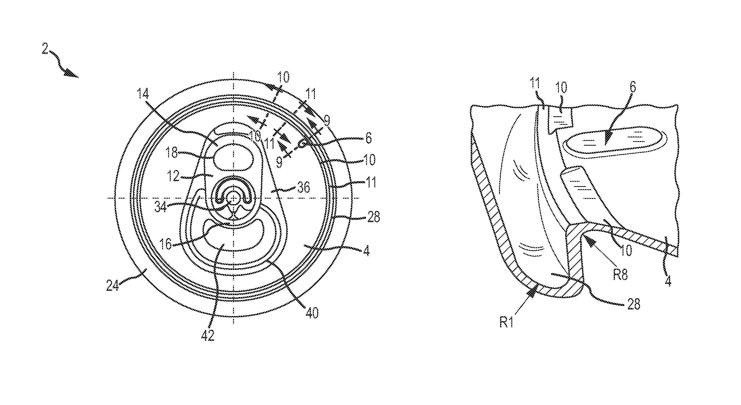
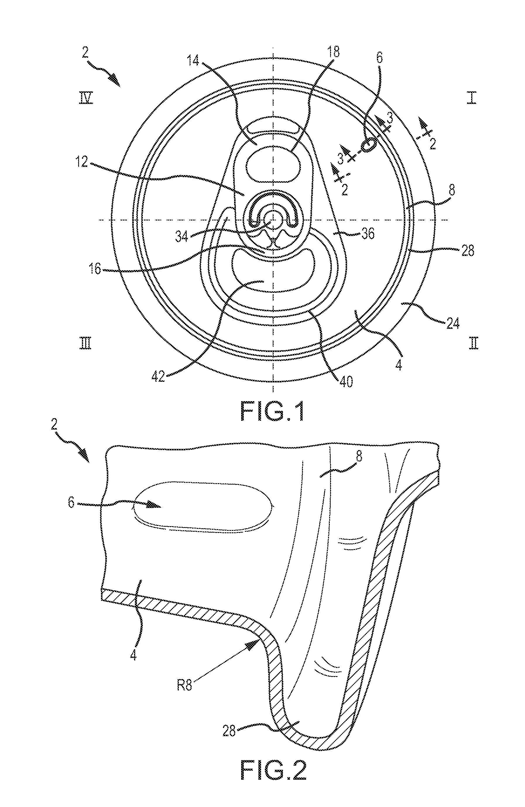
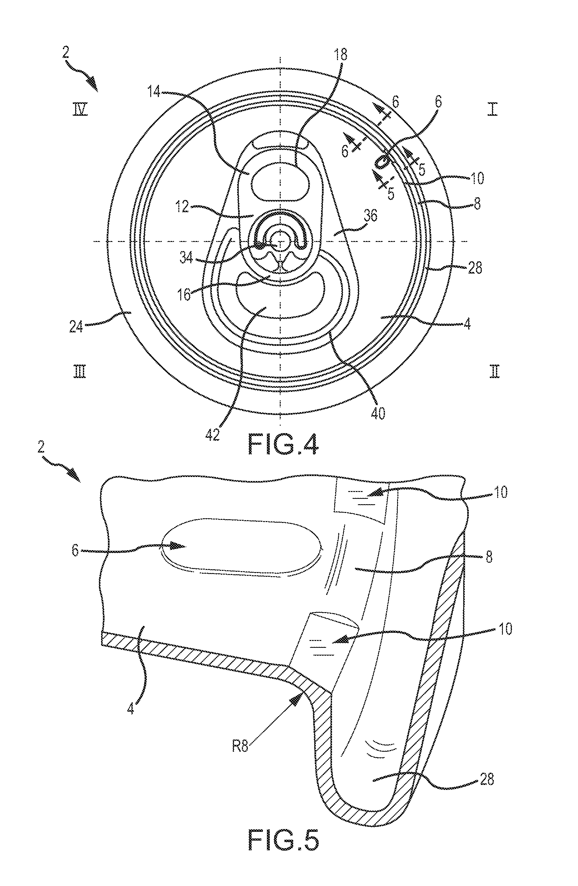
[0068]FIG. 4 illustrates the public side of an end closure 2 with controlled buckling characteristics. The end closure2 may comprise a central panel 4, a panel radius 8, a tab 12, and a countersink 28 interconnected to a chuck wall interconnected to a peripheral curl 24. The tab 12 may comprise a tab nose 16 opposite a tab tail 14 and a lift ring 18. The tab 12 may be interconnected to the central panel 4 using a rivet 34. The central panel 4 may comprise an induced buckle coin 6, a deboss area 36, and a score line 40 defining a tear panel or pour opening 42.

[0069]More specifically, FIG. 4 shows the end closure 2 of FIG. 1 after an interrupted panel coin 10 has been manufactured into the panel radius 8 of the end closure 2. The interrupted panel coin 10 may also be called a “non-continuous panel coin” herein. The interrupted panel coin 10 may or may not actually be coined. The interrupted panel coin 10 is positioned proximate to the peripheral edge of the central panel 4 and is less...

third embodiment

[0074]FIG. 7 shows the public side of an end closure 2. The end closure 2 may comprise a central panel 4, a tab 12, and a countersink 28 interconnected to a chuck wall interconnected to a peripheral curl 24. The tab 12 may comprise a tab nose 16 opposite a tab tail 14 and a lift ring 18. The tab 12 may be interconnected to the central panel 4 using a rivet 34. The central panel 4 may comprise an induced buckle coin 6, a deboss area 36, and a score line 40 defining a tear panel or pour opening 42.

[0075]More specifically, FIG. 7 shows the end closure 2 after a continuous panel coin 11 that extends 360° around the central panel 4 has been manufactured into the panel radius, which is positioned between the central panel 4 and the countersink 28 inner panel wall 32. The end closure 2 of FIG. 7 has a continuous panel coin 11, whereas the end closure of FIG. 4 has a rounded panel radius 8. The continuous panel coin 11 is a primary coined region which extends continuously around the outer p...

fourth embodiment

[0083]FIG. 12 shows the public side of an end closure 2. The end closure 2 generally comprises a central panel 4, a pull tab 12, and a countersink 28 interconnected to a chuck wall interconnected to a peripheral curl 24. The pull tab 12 may comprise a tab nose 16 opposite a tab tail 14 and a lift ring 18. The tab 12 is typically interconnected to the central panel 4 using a rivet 34. The central panel 4 may comprise an induced buckle coin 6, a deboss area 36, and a score line 40 defining a tear panel or pour opening 42.

[0084]FIG. 12 additionally depicts the end closure 2 with a continuous panel coin 11 that extends 360° around the central panel 4 that has been manufactured proximate to the peripheral edge of the central panel 4. The end closure 2 of FIG. 12 has a continuous panel coin 11, and a rounded panel radius (not labeled in FIG. 12). The continuous panel coin 11 is a primary coined region which extends continuously around the entire outer peripheral edge of the central panel ...


PUM

PropertyMeasurementUnit
widthaaaaaaaaaa
internal pressuresaaaaaaaaaa
lengthaaaaaaaaaa

Abstract

An end closure for food and beverage containers is provided. The end closure comprises a central panel portion having an induced buckle coin and an interrupted panel coin positioned proximate to an inner panel wall to control the buckling location on the end closure. Thus, the end closure will buckle at a predetermined location away from the score and tear panel to avoid catastrophic failure and container leakage.

Description

RELATED APPLICATIONS[0001]This application claims the benefit of U.S. Provisional Patent Application Ser. No. 61 / 798,301, filed Mar. 15, 2013, entitled “Container End Closure with Buckle Control Feature,” which is hereby incorporated by reference in its entirety.FIELD OF THE INVENTION[0002]Embodiments of the present invention generally relate to containers and container end closures, and more specifically metallic beverage container end closures with buckle control features.BACKGROUND OF THE INVENTION[0003]Containers, and more specifically metallic beverage containers, generally contain a neck on an upper portion that is adapted for interconnection to a metallic end closure. The container end closure is formed from a flat sheet of metallic material and generally includes a pull tab or other form of stay on tab (“SOT”). Beverage containers commonly store carbonated beverages, thus, both the container body and the container end closure are required to withhold internal pressures up to...

Claims


Application Information

Patent Timeline
Patent Type & Authority Patents(United States)
IPC IPC(8): B65D17/34B65D17/00B21D51/44
CPCB21D51/44B65D17/165B65D2517/0014B65D2517/0068B65D2517/0074B65D2517/0089Y10T29/49863B65D17/4012
Inventor CHASTEEN, HOWARD C.JACOBER, MARK A.
Owner BALL CORP
Why Eureka
Try Eureka