Hinge assembly

a technology of hinges and parts, applied in the field of hinges, can solve the problems of no space or location, inconvenient assembly, and inconspicuous devices, and achieve the effect of avoiding permanent damage, and avoiding damage to devices

Active Publication Date: 2014-03-04
HINGES & HARDWARE LLC
View PDF26 Cites 11 Cited by
  • Summary
  • Abstract
  • Description
  • Claims
  • Application Information

AI Technical Summary

Benefits of technology

[0006]In accordance with a further preferred embodiment of the invention, the hinge assembly includes a force relief mechanism to prevent catastrophic failure of the hinge in the event substantial force is applied to the gate while the hinge assembly is in the locked position. Due to the large moment arm that is created by the gate itself, forces input to the gate are greatly amplified at the hinge and malfunction or permanent damage may arise without some mechanism to relieve these forces. In one form, the relief mechanism utilizes a set screw positioned to maintain the locking function of the hinge assembly, but allowing the two hinge leaves to rotate even when in the locked position upon application of substantial gate closing forces.

Problems solved by technology

When not in use, the device is inconspicuous and occupies no space or location which might prove inconvenient.
Due to the large moment arm that is created by the gate itself, forces input to the gate are greatly amplified at the hinge and malfunction or permanent damage may arise without some mechanism to relieve these forces.

Method used


Image

  • Hinge assembly
  • Hinge assembly
  • Hinge assembly

Examples


Embodiment Construction

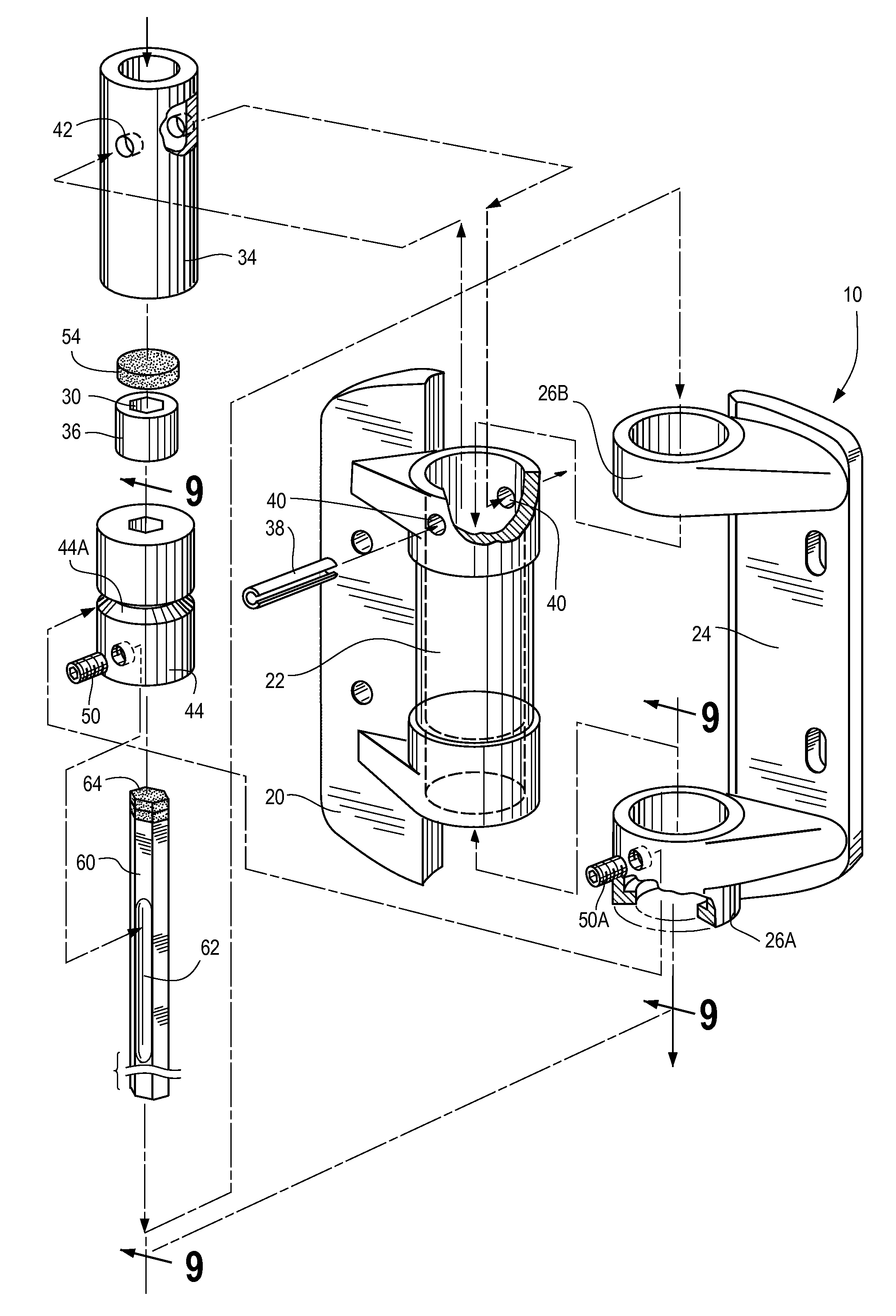
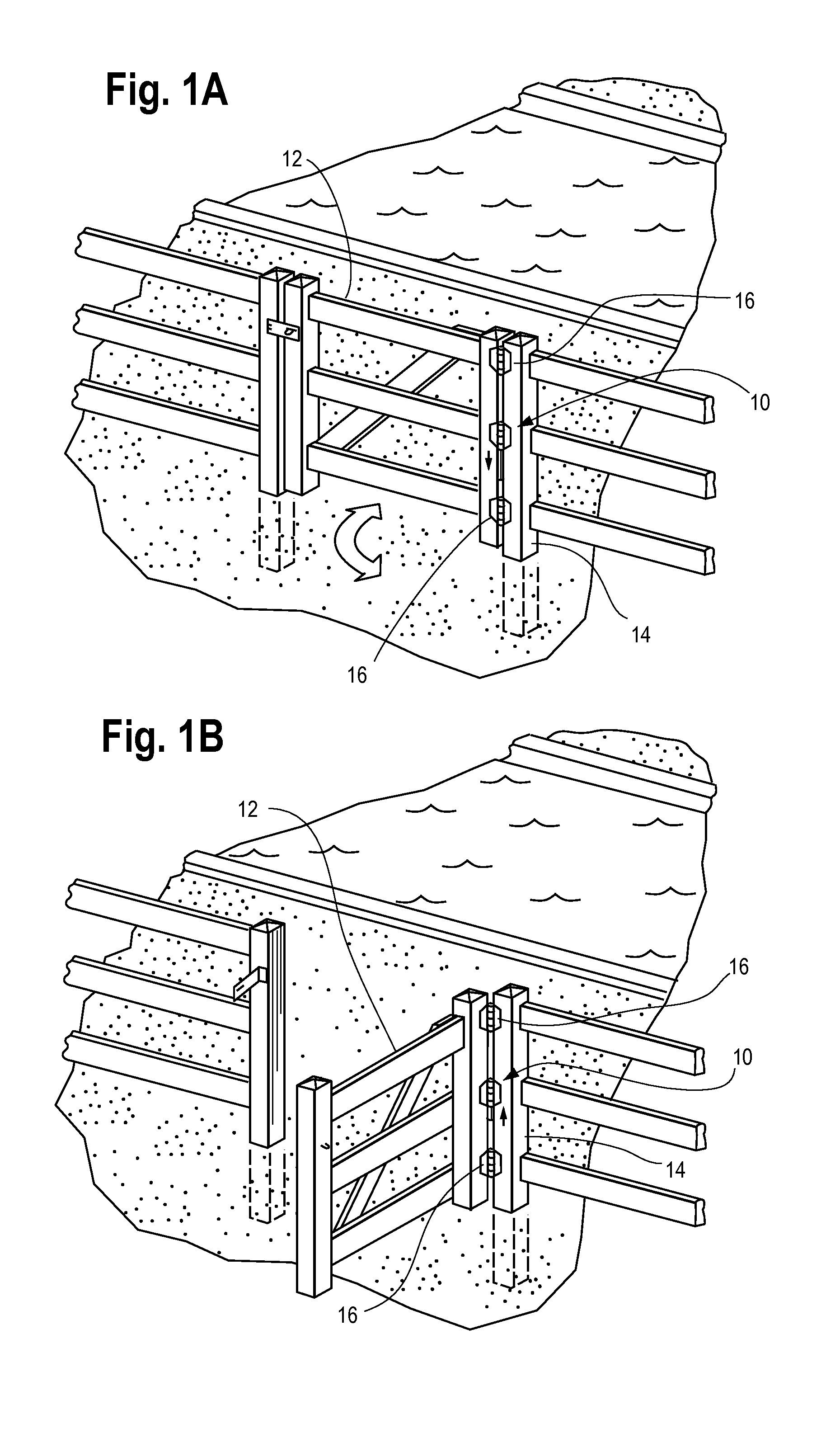
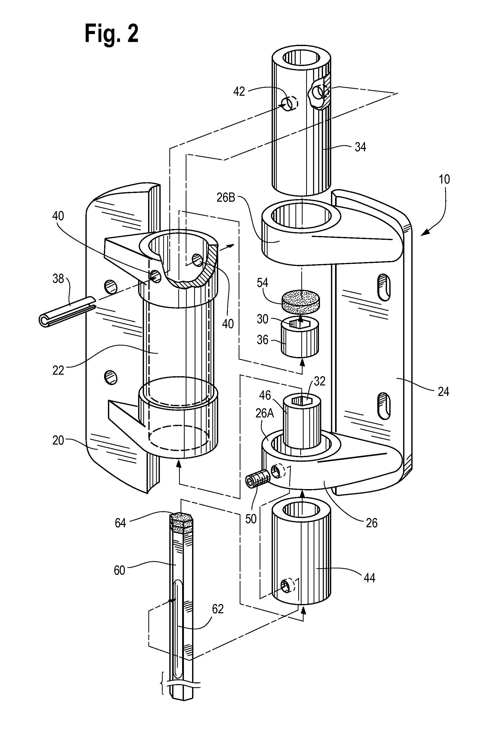
[0019]With reference to Figs. 1A and 1B, a hinge assembly 10, made in accordance with one preferred embodiment of the present invention, is shown in a typical installation on a gate 12 forming part of an enclosure for a swimming pool. The gate 12 is mounted to a gate post 14 by hinge assembly 10 and self closing hinges 16. The self closing hinges 16 include a spring biasing mechanism so that when the gate is opened it will automatically return to the closed position. The hinge assembly 10 includes components that allow the gatel2 and hinges 16 to swing freely to and from a closed position, shown in FIG. 1A, and an open. position, shown in FIG. 1B. In addition, hinge assembly 10 includes components that, when actuated as discussed further below, will hold the gate 12 in the open position against the biasing forces of hinges 16. Of course, the invention may be used in other environments and with any structure where a need exists for maintaining the structure in a fixed rotational orie...


PUM


Abstract

A hinge assembly is movable between open and closed positions and capable of being locked in an open position. The hinge assembly comprises first and second hinge members including, respectively, first and second body portions. A hinge pin assembly cooperates with the hinge members and has aligned internal bores and a longitudinal axis about which the hinge members rotate. A locking pin is movable within the internal bores between a first position and a second position. When the locking pin is in the first position the hinge members cannot rotate relative to one another, and when the locking pin is in the second position the hinge members can rotate relative to one another. A magnetic latch member is mounted to one of the hinge members to hold the locking pin in one of the first or second positions. The locking components may include a mechanical override device to prevent damage.

Description

[0001]This application is a continuation in part of U.S. patent application Ser. No. 13 / 400,803, filed Feb. 21, 2012.BACKGROUND OF THE INVENTION[0002]The present invention relates generally to hinges and, more particularly, to a hinge assembly useful in stopping or preventing the movement of a structure carried by the hinge or with which the hinge is operationally affixed. The present invention finds useful application when used with gates that form a part of the enclosure for swimming pools or other potentially hazardous sites, where building codes often require the use of self closing gates to minimize the hazard to children.[0003]It is known in the art that such self closing gates pose an inconvenience in circumstances where continuing ingress and egress from the enclosed area is desired. For example, when a pool or yard is being serviced, the service personnel often have a need to enter and leave the area while carrying equipment and service implements. At such times, it is much...

Claims


Application Information

Patent Timeline
Patent Type & Authority Patents(United States)
IPC IPC(8): E05D11/10
CPCE05D3/02E05D11/1007E05Y2201/46
Inventor JABLONSKI, PAUL
Owner HINGES & HARDWARE LLC
Why Eureka
Try Eureka