Portable pneumatic compression riveter

a technology of compression riveter and needle roller, which is applied in the direction of manufacturing tools, forging press details, forging presses, etc., can solve the problems of damage to the work being assembled, the crushing of needle rollers, etc., and achieve the effect of lightening and improving reliability of seal design

Active Publication Date: 2006-11-02
HEROD JAMES R
View PDF8 Cites 9 Cited by
  • Summary
  • Abstract
  • Description
  • Claims
  • Application Information

AI Technical Summary

Benefits of technology

[0014] Portable pneumatic compression riveters consist of a valve assembly, cylinder assembly with at least one chamber and a head assembly consisting of an alligator style set of jaws or a c-yoke style jaw set. An air line is connected to the valve assembly. The valve is manually actuated by means of a lever allowing air to flow into the cylinder. In the improvement the valve body is of a composite material with an integrated handle improving ergonomics and significantly reducing the weight. The bulkheads separating the chambers in the cylinder assembly are also made of a composite material that seals each chamber with an o-ring and quad-ring. The pistons are also made of a composite material and used with one or more u-rings to seal the piston—cylinder assembly. Use of the u-rings allows the use of an aluminum cylinder with the composite pistons taking most of the wear. The u-rings allow for a significantly larger amount of wear than does a piston with an o-ring; this contributes significantly to extend the service life interval. Further, since composite pistons are used, the cylinder can be made of aluminum without the benefit of hard anodize applied to the interior of the cylinder or using a steel cylinder to address cylinder wear and seal problems.
[0015] In another aspect of the invention, the wedge is pinned within a clevis that is mounted to the face of the piston. The wedge, driven forward by the compressed air behind the piston, is forced between a set of bearings causing the pivoting jaw to pivot about the center pin resulting in a squeezing action out on the end of the pivoting jaw as it closes with the fixed jaw. In the improvement, the wedge has angled flats on the nose which allow the wedge to self align as it moves forward rather than bind in the rivet head assembly. The wedge's construction is such that it is pocket milled on both sides creating an I-beam cross section which contributes to a lighter tool.
[0016] In another aspect of the invention, an improvement is made by utilizing a hardened steel sleeve, instead of a needle roller bearing at the pivot pin, to eliminate the problems with crushed needle rollers and also contribute to a lighter, more reliable and compact tool.
[0017] In yet another embodiment of the invention, an improvement is made by adding a hollow recess to the pivoting jaw just above and behind the pivot pin with the purpose of allowing a fatigue crack to propagate into the hollow recess thus preventing a catastrophic failure of the forward portion of the pivoting jaw from becoming a projectile that could cause injury to the operator or damage to the work being assembled.

Problems solved by technology

Crushing these needle rollers has long been a limiting factor for this type of tool.
Another shortcoming of the portable pneumatic compression riveters produced today is the potential for catastrophic failure of the pivoting jaw which can lead to injury or damage to the work being assembled when the forward portion of the pivoting jaw reaches its fatigue limit and breaks off from the attached portion at or around the pivot pin area.

Method used


Image

  • Portable pneumatic compression riveter
  • Portable pneumatic compression riveter
  • Portable pneumatic compression riveter

Examples


Embodiment Construction

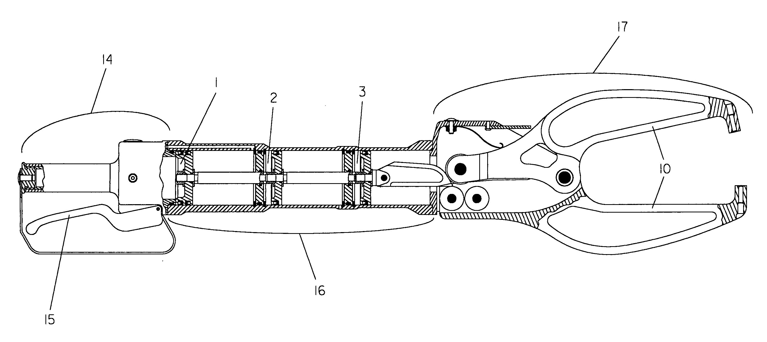
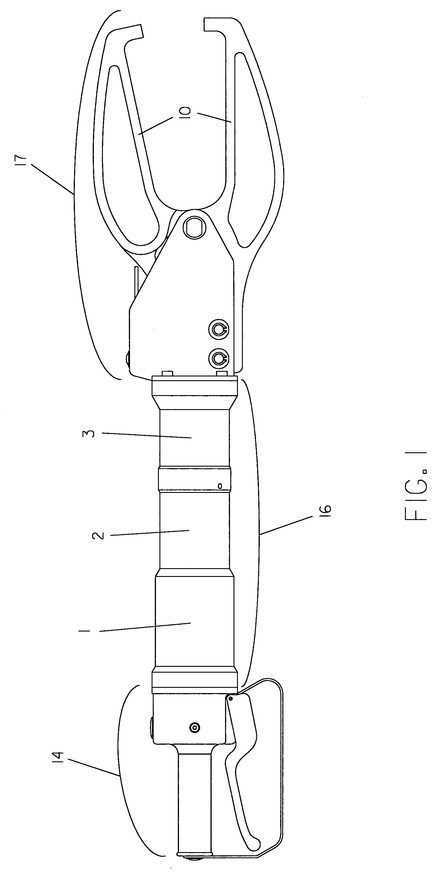
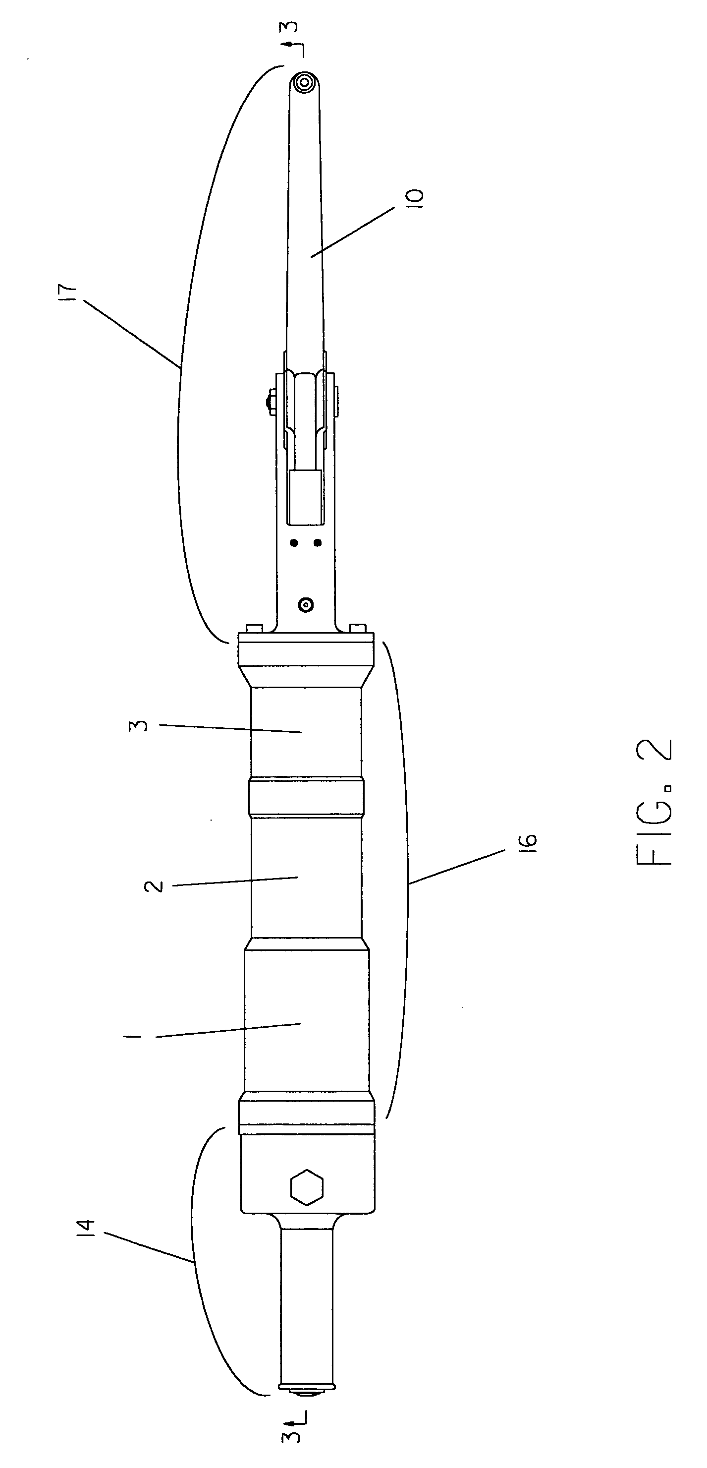
[0032] Referring first to FIGS. 1, 2, 3 and 4 an exemplary portable pneumatic compression riveter is depicted which includes a valve assembly 14, cylinder assembly 16 with more than one chamber (3 chambers in this representation identified here as chambers 1, 2 and 3), and a rivet head assembly 17. FIGS. 1, 2, 3 and 4 show the compression riveter fitted with an al1igator set of jaws 10. The exemplary portable pneumatic compression riveter includes the preferred embodiments disclosed in this document. FIG. 3 shows the compression riveter prior to the lever 15 on the valve assembly 14 being actuated with the alligator jaw set 10 open. FIG. 4 shows the compression riveter with the lever 15 on the valve assembly 14 actuated and the alligator jaw set 10 closed. When the lever 15 is released the alligator jaw set 10 opens and the compression riveter resets as shown in FIG. 3.

[0033] Additionally, FIG. 5 shows the composite valve body 12 with the integrated handle. The composite valve body...


PUM

PropertyMeasurementUnit
pressureaaaaaaaaaa
diameteraaaaaaaaaa
air pressureaaaaaaaaaa

Abstract

A portable pneumatic compression riveter consists of a valve, air cylinder and rivet head assembly consisting of an alligator style set of jaws or a c-yoke style jaw set that is used to upset solid rivets used primarily, but not limited to, the aerospace industry. Disclosed is a series of improvements that make the tool lighter, more reliable and safer to operate.

Description

BACKGROUND OF THE INVENTION [0001] 1. Field of the Invention [0002] This invention relates generally to portable pneumatic tools and, more particularly, to compression riveters, used to install solid rivets primarily but not limited to the aerospace industry. [0003] 2. Description of the Related Art [0004] Portable pneumatic compression riveters are used to install solid rivets to join parts together. They consist of a valve assembly, cylinder assembly with at least one compression chamber and a head assembly consisting of an alligator style set of jaws or a c-yoke style jaw set. An air line with approximately 90 psi compressed air is connected to the valve. The valve is manually actuated by means of a lever allowing compressed air to enter the cylinder assembly. Inside the cylinder, a piston with a seal and a wedge attached to the front is driven forward by the compressed air. The wedge is driven between a set of bearings mounted within the jaws of the rivet head assembly. The wedg...

Claims


Application Information

Patent Timeline
Patent Type & Authority Applications(United States)
IPC IPC(8): B21J9/18
CPCB21J15/10Y10T29/5377B21J15/18B21J15/16
Inventor HEROD, JAMES R.
Owner HEROD JAMES R
Why Eureka
Try Eureka