Burst plug

a technology of overpressure relief and burst plugs, which is applied in the direction of functional valve types, shoelace fastenings, transportation and packaging, etc., can solve the problems of causing shrapnel to burst and high price of rupture discs, so as to prevent catastrophic failure of systems and relieve internal pressur

Inactive Publication Date: 2010-11-11
PARKER HANNIFIN CORP
View PDF22 Cites 11 Cited by
  • Summary
  • Abstract
  • Description
  • Claims
  • Application Information

AI Technical Summary

Benefits of technology

[0006]A piston can be provided internal to the plug and includes an end wall with the shear portion. The shear portion can be formed such as by the geometry of the wall (e.g., a relatively thin portion), and / or by a feature such as a score line. The piston can be mechanically retained within an internal cavity of the plug, and an O-seal can be provided between the piston and plug body to provide a fluid-tight seal. The relief passage(s) in the plug can have a geometry, e.g., an axial or radial passage intersecting a main cavity at an angle or offset from a central axis, and / or set dimensions smaller than the shear portion to prevent the shear portion from exiting to the external environment. Fluid internal to the plug is allowed to flow out through the relief passage(s) when the shear portion ruptures, thus relieving the internal pressure and preventing catastrophic failure of the system.

Problems solved by technology

Rupture discs can be expensive and may produce shrapnel upon burst.

Method used


Image

  • Burst plug
  • Burst plug
  • Burst plug

Examples


Embodiment Construction

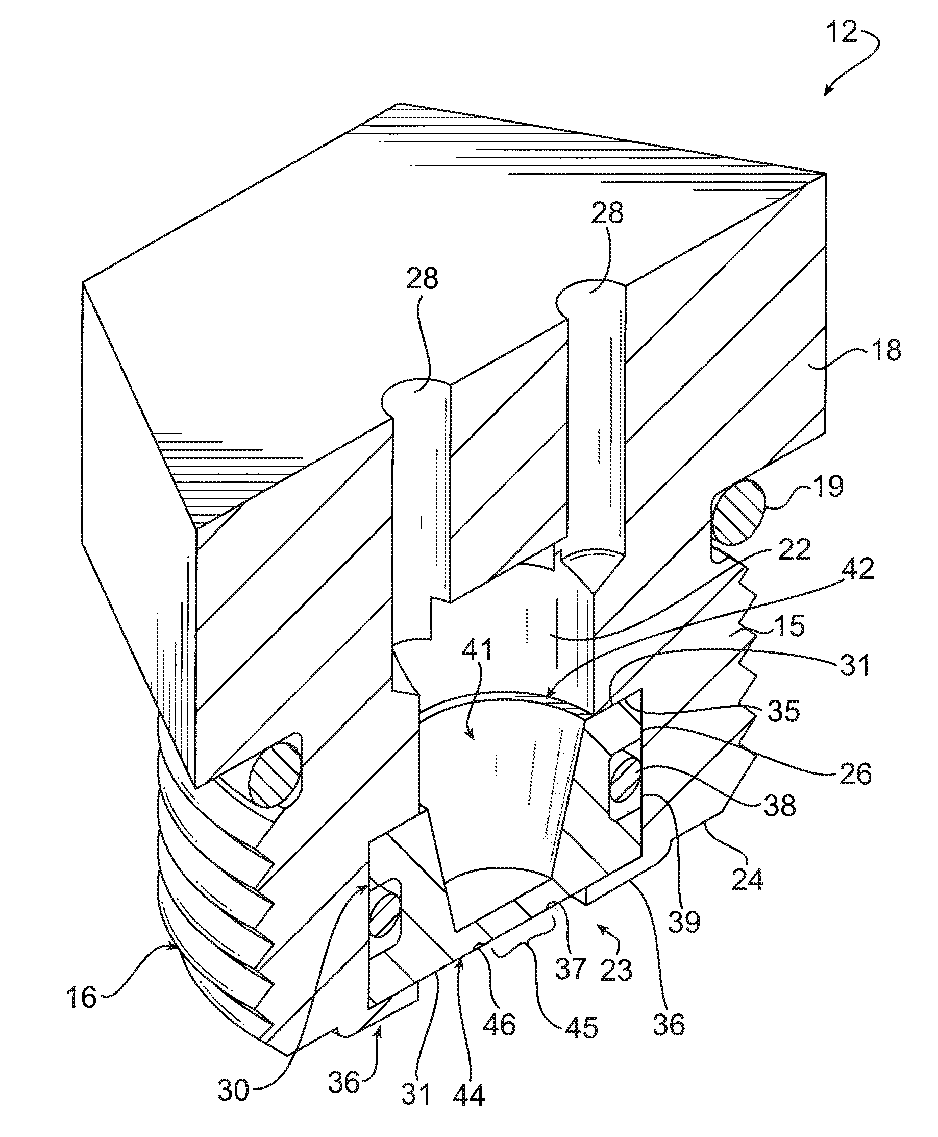
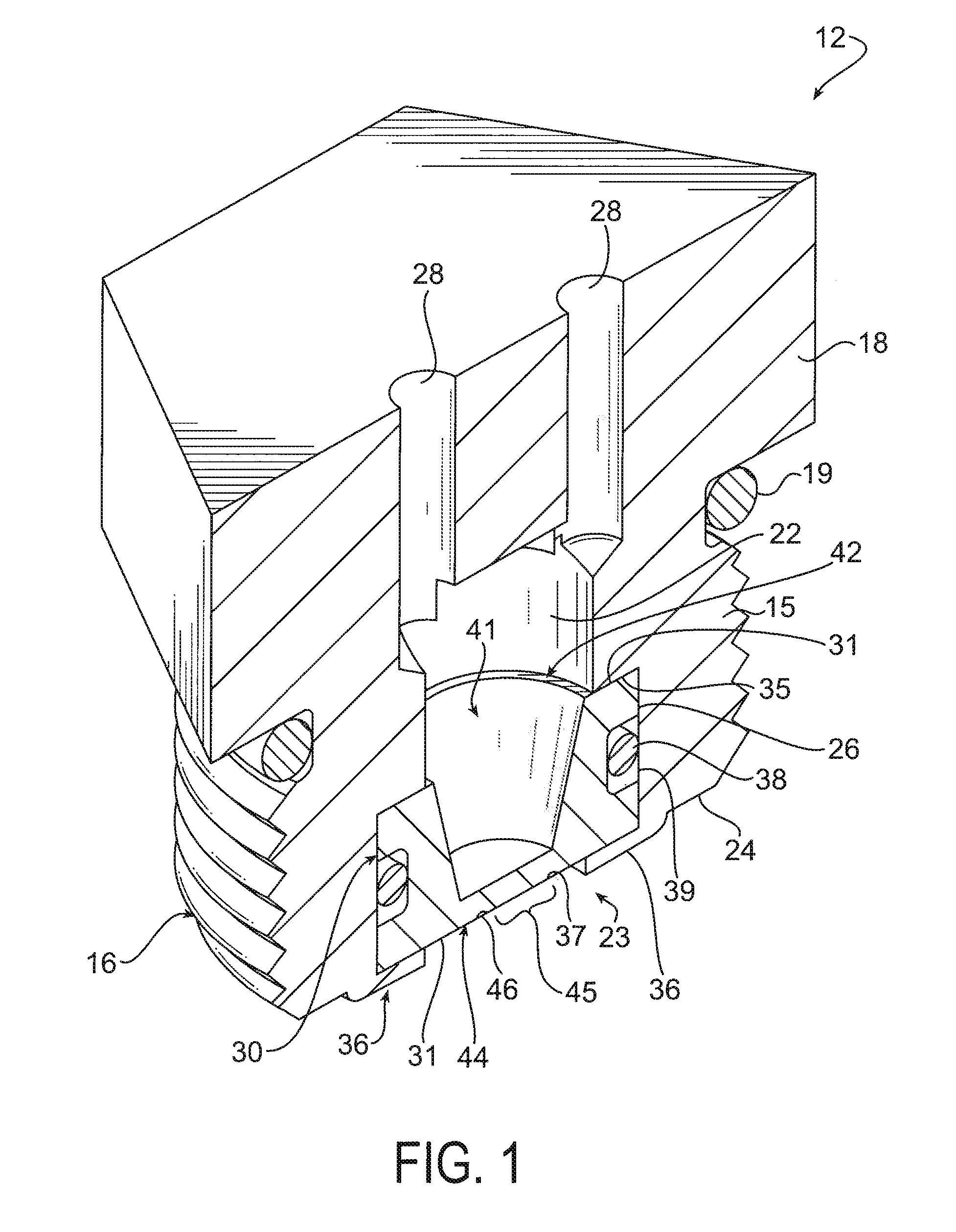
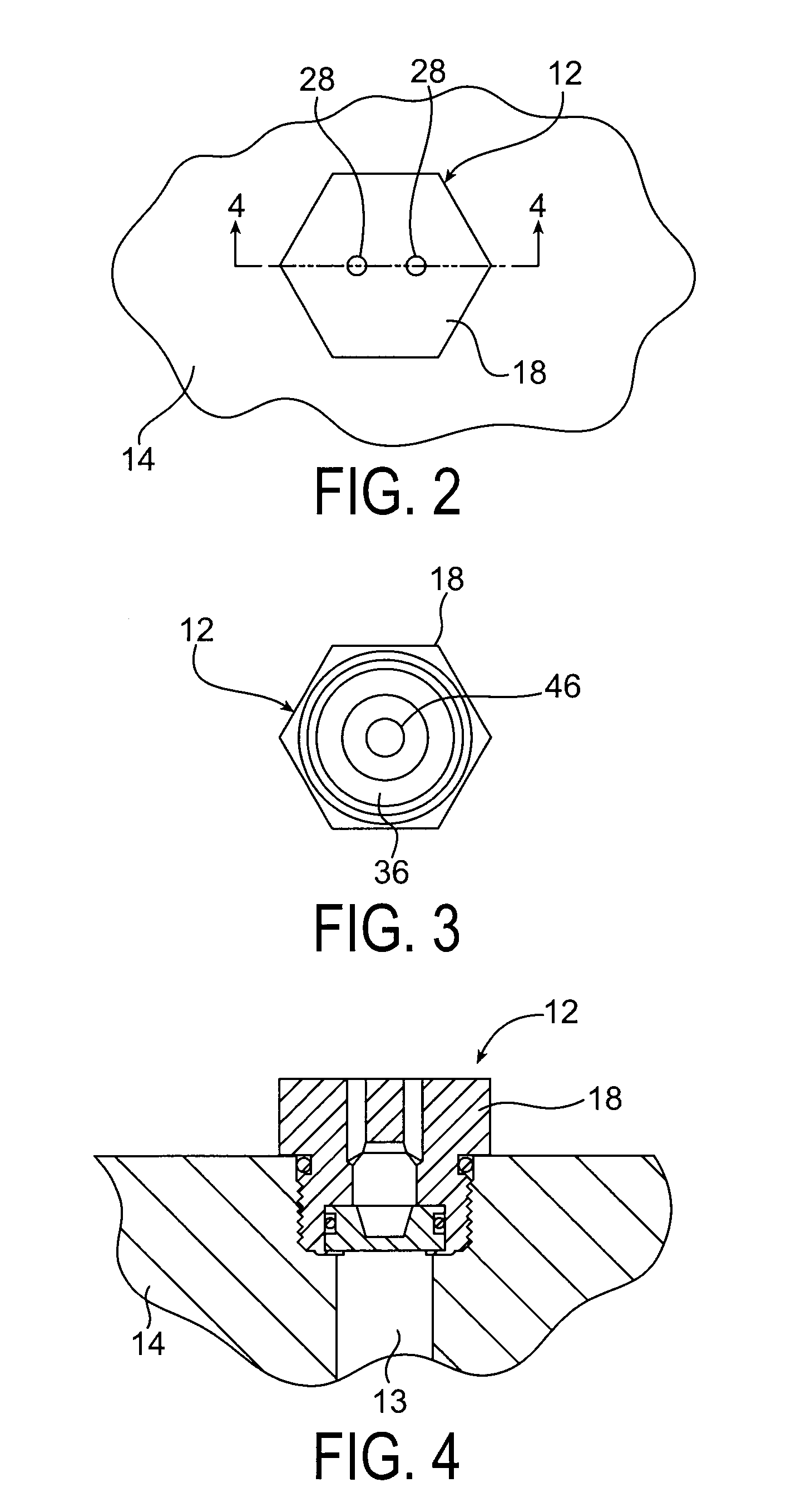
[0015]Referring to the drawings, and initially to FIGS. 1-4, a plug device is shown generally at 12, constructed according to the principles of the present invention.

[0016]The plug (also referred to as a “fitting” or “connection”) can be directly installed into a port 13 of a product, indicated generally at 14 (e.g., a filter, pump, manifold block, etc) as should be appreciated by those skilled in the art. The port 13 can betheraded or have other means for retaining the plug. The plug encloses the port 13 and normally prevents fluid leakage therefrom.

[0017]The plug 12 includes an annular body 15 which is externally threaded as at 16; and a flat head 18 at its top which is preferably enlarged and includes appropriate geometry (such as the illustrated peripheral hex geometry) as is typical for such a plug to allow the head to be manipulated by a tool such as a wrench, to screw the plug into and out of the threaded port 13. An O-ring seal 19 can be provided, if necessary or appropriate...


PUM


Abstract

A plug for a fluid system includes an externally-threaded body and an enlarged head at an end of the body. The body has an internal cavity with a) a first fluid passage into the cavity from another end of the body, and b) at least one radial or axial relief passage into the cavity fluidly separate from the first passage. A burst piston is retained within the cavity and normally blocks fluid flow from the first passage to the relief passage. The piston has a geometry such that a portion of the piston will rupture and separate from the remainder of the piston at a predetermined pressure differential across the first and relief passages, and allow fluid to flow from the first passage to the relief passage. The relief passage has a geometry to prevent the separated portion of the piston from passing through the relief passage.

Description

CROSS REFERENCE TO RELATED APPLICATIONS[0001]The present application claims the benefit of the filing date of U.S. Provisional application Ser. No. 61 / 175,559, filed May 5, 2009, the disclosure of which is incorporated herein by reference in its entirety.FIELD OF THE INVENTION[0002]The present invention relates generally to overpressure relief devices in fluid systems, which relieve fluid when the pressure in the system exceeds a predetermined level.BACKGROUND OF THE INVENTION[0003]Relief valves and rupture disks are known in the fluid industry to provide a relief passage to prevent over-pressure in a system from causing catastrophic failure of the system, e.g., rupturing a containment vessel in the system. Relief valves and rupture discs are independent components that must be specified, purchased, and installed in the system. In most cases, their installation requires additional devices, plumbing, etc. These devices can also require proper set points to be safe, and must be inspec...

Claims


Application Information

Patent Timeline
Patent Type & Authority Applications(United States)
IPC IPC(8): F16K17/40
CPCA43C1/00A43B1/0027Y10T137/1632F16L55/07F16L55/1108
Inventor LUTHER, KENNETH M.GEMBOLIS, DONALD J.
Owner PARKER HANNIFIN CORP
Why Eureka
Try Eureka