
Thin film depositing apparatus

a technology of depositing apparatus and film, which is applied in the direction of manufacturing tools, arms, transportation and packaging, etc., can solve the problems of reducing productivity and achieve the effect of increasing or maximizing productivity

Active Publication Date: 2015-08-25
ELECTRONICS & TELECOMM RES INST
View PDF11 Cites 0 Cited by
  • Summary
  • Abstract
  • Description
  • Claims
  • Application Information

AI Technical Summary

Benefits of technology

[0005]The present invention also provides a thin film depositing apparatus increasing or maximizing productivity.

Problems solved by technology

However, since the typical cluster type sputtering system needs to sequentially perform a process of a single substrate, its productivity may be reduced.

Method used


Image

  • Thin film depositing apparatus
  • Thin film depositing apparatus
  • Thin film depositing apparatus

Examples


Embodiment Construction

[0023]Preferred embodiments of the present invention will be described below in more detail with reference to the accompanying drawings. The present invention may, however, be embodied in different forms and should not be constructed as limited to the embodiments set forth herein. Rather, these embodiments are provided so that this disclosure will be thorough and complete, and will fully convey the scope of the present invention to those skilled in the art. Like reference numerals refer to like elements throughout.

[0024]While specific terms were used, they were not used to limit the meaning or the scope of the present invention described in Claims, but merely used to explain the present invention. The meaning of “include,”“comprise,”“including,” or “comprising,” specifies a property, a region, a fixed number, a step, a process, an element and / or a component but does not exclude other properties, regions, fixed numbers, steps, processes, elements and / or components. Since preferred em...


PUM

PropertyMeasurementUnit
vacuum pressureaaaaaaaaaa
lengthaaaaaaaaaa
widthaaaaaaaaaa

Abstract

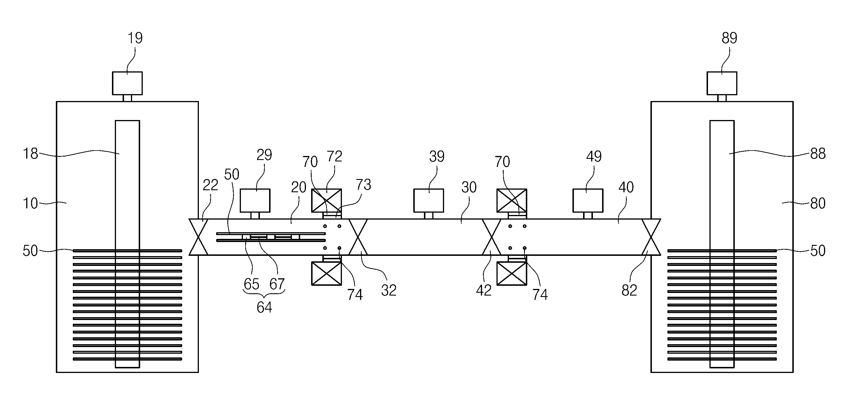
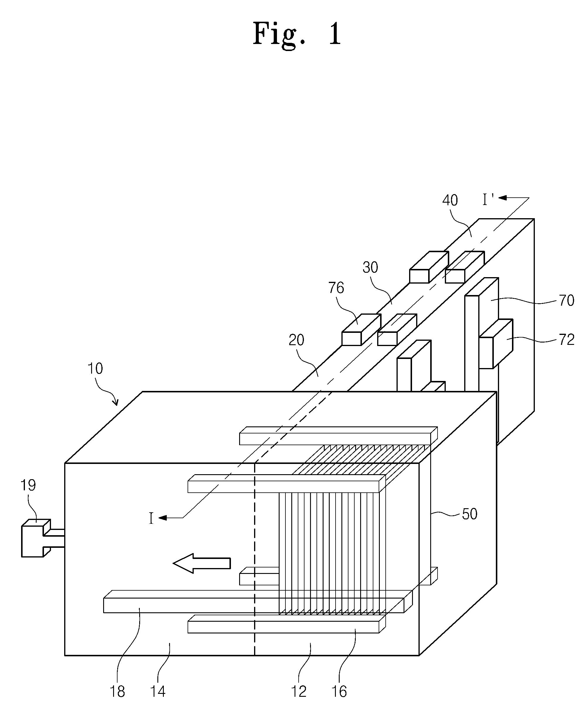
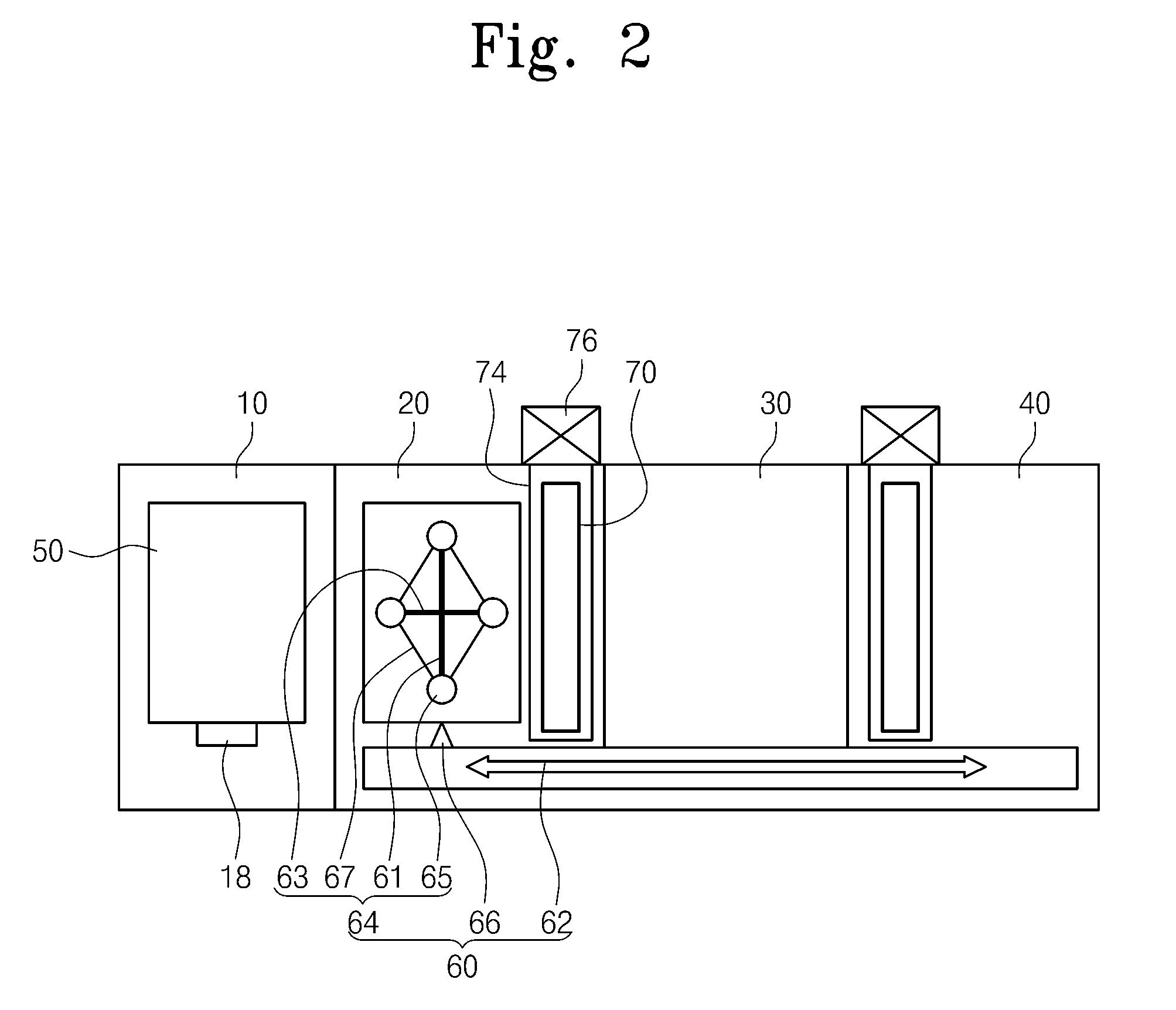
Provided is a thin film depositing apparatus. The thin film depositing apparatus includes: a loading chamber loading a plurality of substrates; a first process chamber connected to the loading chamber and including a plurality of sputter guns inducing a first plasma on the plurality of substrates; a buffer chamber connected to the other side of the first process chamber facing the loading chamber; and a substrate transfer module simultaneously passing the plurality of substrates between the plurality of sputter guns during a process using the first plasma and transferring the plurality of substrates from the first process chamber to the buffer chamber.

Description

CROSS-REFERENCE TO RELATED APPLICATIONS[0001]This U.S. non-provisional patent application claims priority under 35 U.S.C. §119 of Korean Patent Application No. 10-2010-0101510, filed on Oct. 18, 2010 and 10-2010-0131427, filed on Dec. 21, 2010, the entire contents of which are hereby incorporated by reference.BACKGROUND OF THE INVENTION[0002]The present invention disclosed herein relates to a thin film depositing apparatus, and more particularly, to a thin film depositing apparatus depositing a thin film on a film or a flat plate.[0003]A high-performance thin film becomes greatly utilized because of development of electronic communication technology. Moreover, Research and Development (R&D) for mass production of the high-performance thin film is actively in progress. A typical thin film depositing apparatus may include a cluster type multi sputtering system. In relation to the cluster type sputtering system, a plurality of process chambers may be disposed with a shape of a square, ...

Claims


Application Information

Patent Timeline
Patent Type & Authority Patents(United States)
IPC IPC(8): C23C16/44H01L21/67C23C14/56C23C14/34H01L21/677C23C16/458B25J15/06B25J18/00
CPCC23C16/4587C23C14/34C23C14/568H01L21/6776H01L21/67173H01L21/67712H01L21/67718H01L21/67751
Inventor CHEONG, WOO-SEOK
Owner ELECTRONICS & TELECOMM RES INST
Learn More