
Optical tomographic imaging apparatus and imaging method therefor to acquire images indicating polarization information

a tomographic imaging and optical tomography technology, applied in the field of optical tomographic imaging apparatus, can solve the problems of affecting the accuracy of polarization parameter calculation, and achieve the effect of simplifying optical setup and accurate polarization parameters

Inactive Publication Date: 2015-08-25
CANON KK
View PDF62 Cites 3 Cited by
  • Summary
  • Abstract
  • Description
  • Claims
  • Application Information

AI Technical Summary

Benefits of technology

The present invention allows for the alignment of beams with different polarization directions. This results in an optical tomographic imaging apparatus that can capture accurate polarization parameters and produce a polarization OCT image with a simplified optical setup. The invention also provides an imaging method for the optical tomographic imaging apparatus.

Problems solved by technology

Thus, the accuracy in polarization parameter calculation is affected.

Method used


Image

  • Optical tomographic imaging apparatus and imaging method therefor to acquire images indicating polarization information
  • Optical tomographic imaging apparatus and imaging method therefor to acquire images indicating polarization information
  • Optical tomographic imaging apparatus and imaging method therefor to acquire images indicating polarization information

Examples


Embodiment Construction

[0019]Various exemplary embodiments, features, and aspects of the invention will be described in detail below with reference to the drawings.

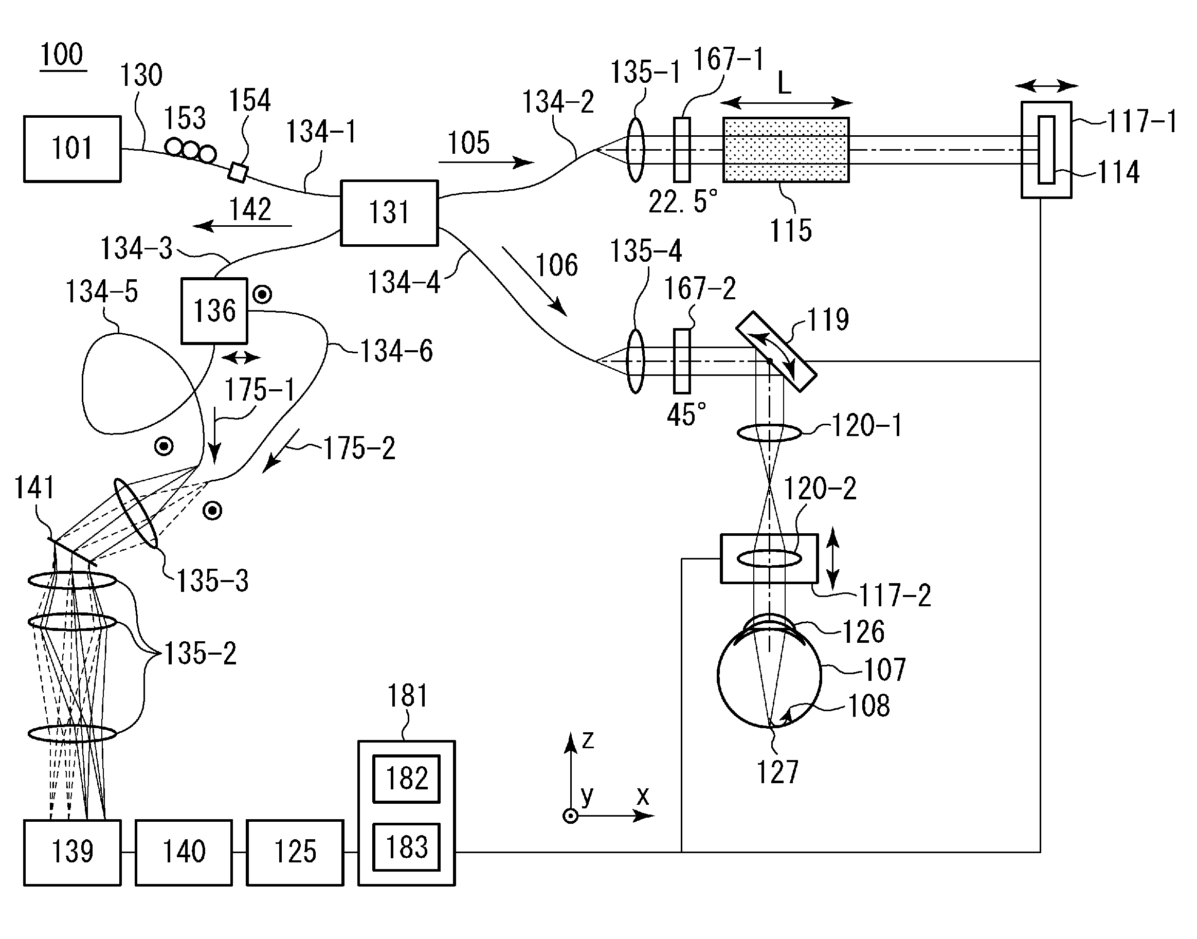
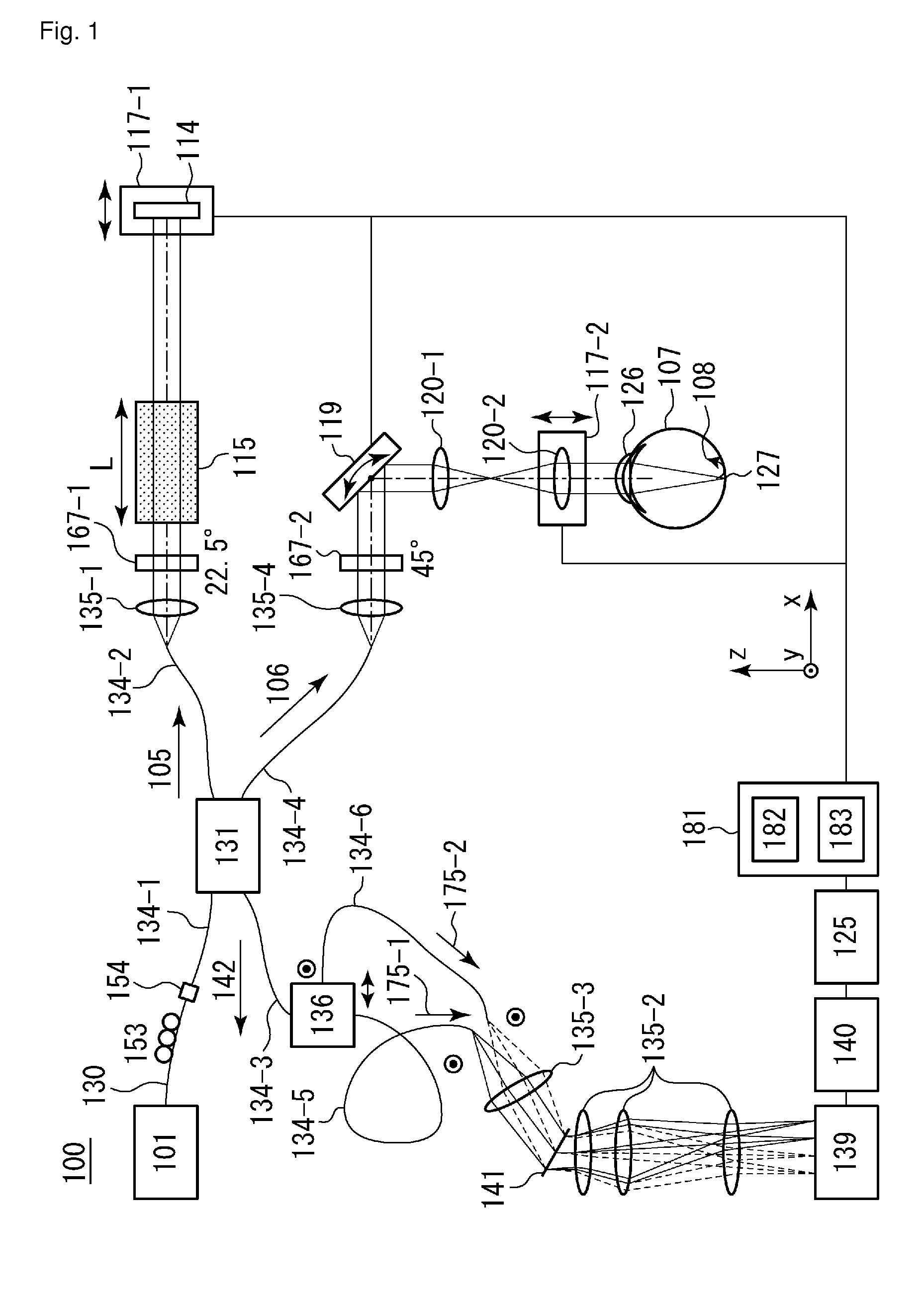
[0020]An imaging apparatus according to the present exemplary embodiment will be described below with reference to FIG. 1. FIG. 1 illustrates a configuration of an OCT apparatus 100 (particularly, a polarization OCT apparatus) according to the present exemplary embodiment.

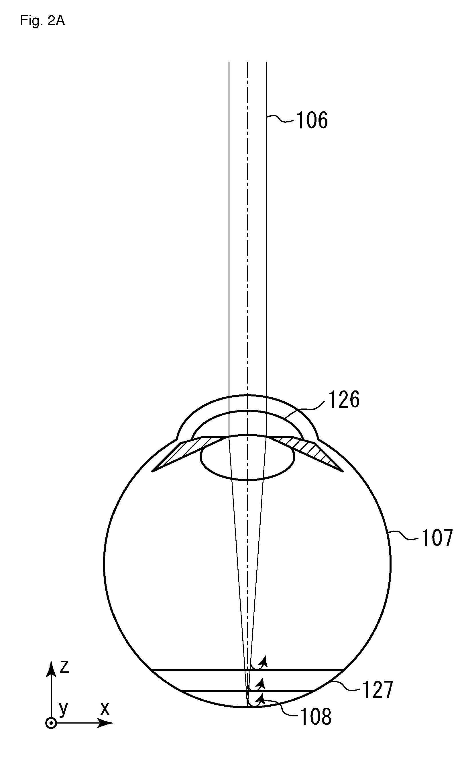
[0021]A return beam 108 comes from a object 107 irradiated with a beam based on a measuring beam 106 (a circularly-polarized beam obtained after the measuring beam 106 passes through a lambda / 4 plate 167-2 disposed with a 45-degree inclination with respect to a measuring beam path). The return beam 108 is combined with a beam based on a reference beam 105 corresponding to the measuring beam 106 (a linearly-polarized beam obtained after the reference beam 105 passes through a lambda / 4 plate 167-1 disposed with a 22.5-degree inclination with respect to a reference beam path) to ...


PUM


Abstract

An imaging apparatus adjusts the polarization directions of irradiation beams (to a diffraction grating) corresponding to first and second beams respectively which have different polarization directions (for example, by adjusting a relative angle formed between light-emitting ends of respective polarization maintaining fibers) so that the spectral characteristics of the irradiation beams at the diffraction grating coincide with each other. Then, the imaging apparatus acquires a tomographic image indicating polarization information for a object based on beams (that come from the diffraction grating for splitting and diffracting a beam from the adjustment unit) corresponding to the first and second beams respectively which have different polarization directions.

Description

TECHNICAL FIELD[0001]The present invention relates to an optical tomographic imaging apparatus and an imaging method for the optical tomographic imaging apparatus. More particularly, the present invention relates to an optical tomographic imaging apparatus for capturing tomographic images used for ophthalmologic examinations, and to an imaging method for the optical tomographic imaging apparatus.BACKGROUND ART[0002]Optical coherence tomography (OCT) using the multiple-wavelength optical interference is a method for obtaining a high-resolution tomographic image of a sample (particularly, the fundus). Hereinafter, an apparatus for capturing a tomographic image by using OCT is referred to as OCT apparatus.[0003]In recent years, OCT apparatuses for ophthalmology have attempted to acquire a functional OCT image for imaging the optical characteristics and movement of the fundus tissue in addition to an ordinary OCT image for imaging the shape of the fundus tissue. A polarization OCT appar...

Claims


Application Information

Patent Timeline
Patent Type & Authority Patents(United States)
IPC IPC(8): G01B9/02A61B3/10A61B5/00
CPCG01B9/02011A61B5/0066G01B9/02027G01B9/02044G01B9/02091A61B3/102G01B2290/65G01B2290/70A61B3/10A61B3/12G01B9/02
Inventor HIROSE, FUTOSHI
Owner CANON KK
Learn More