
Circular polarizer with flexible and variable rotation and braking angles

A circular polarizer and angle technology, applied in the direction of electrical components, antennas, etc., can solve the problems of difficult control of the installation position accuracy of the proximity switch, groove position error, and the electrical connector is easy to be exposed to rain, etc., to achieve the rotation and braking angle. The effect of being flexible, solving sealing and corrosion resistance problems, and reducing the complexity of manufacturing and assembly

Active Publication Date: 2018-07-24
CHINA ELECTRONIC TECH GRP CORP NO 38 RES INST
View PDF3 Cites 3 Cited by
  • Summary
  • Abstract
  • Description
  • Claims
  • Application Information

AI Technical Summary

Problems solved by technology

[0002] like Figure 15 As shown, it is the existing old-fashioned circular polarizer. The existing old-fashioned circular polarizer relies on mechanical triggering and braking. The braking angle is fixed and can only be set at certain angle positions, such as Figure 17 As shown, the brake is locked and cannot be stopped and held in other positions, so the phase of the electromagnetic beam in the waveguide cannot be moved to any non-specific phase angle or polarization direction
[0003] Due to relying on the triggering of the proximity switch 63 installed on the fixed position 62, as Figure 16 As shown, to achieve angle measurement and positioning, the installation position accuracy of the proximity switch is not easy to control, resulting in poor positioning accuracy of the circular polarizer
[0004] For the old-fashioned circular polarizers, which are positioned by sliding the top post 60 into the groove 61, it is difficult to accurately control the position error and manufacturing error of the groove, resulting in frequent manufacturing failures and rework.
The transmission mechanical structure of the old-fashioned circular polarizer is complicated, the reliability is low, the cost of manufacturing, processing and maintenance is high, and the overall equipment is relatively heavy
[0005] The absence of the rainproof groove makes the electrical connector 64 prone to rain and corrosion
[0006] When the wavelength and waveband retransmitted inside the waveguide change, due to the precise mechanical structure, the redesign and modification process of the old circular polarizer is time-consuming and complicated
[0007] The man-machine interface of the old-fashioned circular polarizer is relatively simple and scarce
The dielectric sheet 65 used for polarization work is completely enclosed inside the rotating band tube, and cannot be directly observed outside, resulting in the working angle of the dielectric sheet, which cannot be read intuitively during system debugging and normal operation
It can only be obtained indirectly through electrical parameters. When the relevant electrical parameters fail, it is easy to misjudgment

Method used


Image

  • Circular polarizer with flexible and variable rotation and braking angles
  • Circular polarizer with flexible and variable rotation and braking angles
  • Circular polarizer with flexible and variable rotation and braking angles

Examples


Embodiment approach 1

[0062] Encoder 9 is model 906-28XZ42, encoder coupling 10 and encoder gearbox coupling 12 are coupling SFC-005SA2-3B-3B-M, motor 19 is model Maxon RE25 Among them, 339152 has a rated speed of 10900rpm, and the motor gearbox 20 uses Maxon GP 32A series 166167, and its reduction ratio is 86.

[0063] The reduction ratio of encoder reduction box 11 is 5.2:1. Encoder combination gear 14 has 20 teeth and a modulus of 2.5 mm, waveguide gear 15 has 104 teeth and a modulus of 2.5 mm, so the reduction ratio of the large and small gears is 20 / 104=1 / 5.2. Therefore, the rotational angular velocity of the waveguide assembly 1 is always synchronized with the encoder 9 , which facilitates the encoder 9 to interpret the operating state of the waveguide assembly 1 in real time.

[0064] The rated power of the motor 19 is 20W, the rated torque is 28.8mNm, and the rated speed is 10900rpm.

[0065] The reduction ratio of the gearbox 20 is 86, and the maximum continuous output torque is 4.5Nm. ...

Embodiment approach 2

[0070]Open 5 parallel waist-shaped through holes on the motor support 21, pass these waist-shaped through holes with bolts, drive device 2 including the motor support 21 and the aluminum shell 25 are connected and fixed together (note that the bolts are light It is enough to lightly tighten the belt, do not fix it completely, so as to facilitate the next step of clearance adjustment). Utilizing the swimming adjustment ability of these waist-shaped holes, when hitting the motor support 21 back and forth with a hammer, the gap between the motor combination gear 22 on the driving device 2 and the waveguide gear 15 on the action actuator can be adjusted, and the gap can be adjusted to The proper size can neither cause the drive to be stuck because it is too small or too tight, nor can the gap be too large. In order to avoid large gear backlash and low transmission accuracy, it is more appropriate to control this gap at about 0.01mm. After adjusting the gap properly, tighten the m...

Embodiment approach 3

[0072] Five parallel waist-shaped through holes are opened on the encoder support 13, and bolts pass through these waist-shaped through holes to connect and fix the angle measuring mechanism including the encoder support 13 and the aluminum housing 25 together (note The bolts can be lightly tightened, and should not be completely fixed, so as to facilitate the clearance adjustment in the next step). Utilizing the swimming adjustment ability of these waist-shaped holes, when hitting the encoder support 13 back and forth with a hammer, the gap between the encoder combination gear 14 on the angle measurement mechanism and the waveguide gear 15 on the action actuator can be adjusted, and the gap can be adjusted. Adjust to an appropriate size, neither the drive will be stuck due to too small or too tight, nor the backlash of the gears will be too large due to the gap. In order to avoid large gear backlash and low transmission accuracy, it is more appropriate to control this gap at ...


PUM


Abstract

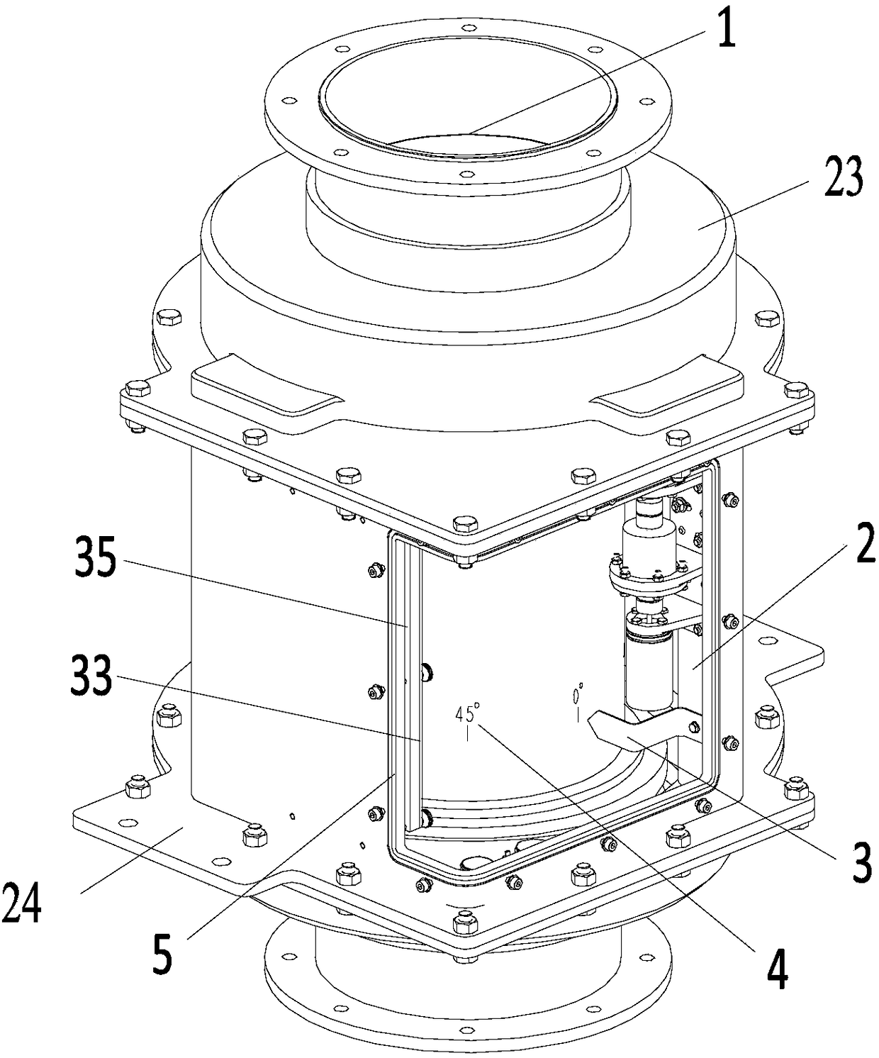
The invention discloses a circular polarizer with flexible and variable rotation and braking angles. The circular polarizer comprises a waveguide tube assembly (1), a driving device (2), an angle measuring mechanism and a printed board (33); the driving device (2) drives the waveguide tube assembly (1) to rotate; the angle measuring mechanism measures the rotation angle of the waveguide tube assembly (1), and transmits the rotation angle to the printed board (33); and the printed board (33) controls the motor of the driving device (2) according to the rotation angle of the waveguide tube assembly (1) and an external input command, so that the rotation angle of the waveguide tube assembly (1) can be controlled. The rotation and braking angles of the circular polarizer of the invention are flexible and variable, so that phase angles and polarization directions can be adjusted and set in a program according to different wavelengths and parameters, and a mechanical structure is not required to be changed.

Description

technical field [0001] The invention belongs to a propagation control, phase adjustment and polarization device of electromagnetic waves, in particular to a circular polarizer. Background technique [0002] like Figure 15 As shown, it is the existing old-fashioned circular polarizer. The existing old-fashioned circular polarizer relies on mechanical triggering and braking. The braking angle is fixed and can only be set at certain angle positions, such as Figure 17 As shown, the brake is locked and cannot be stopped and maintained at other positions, so the phase of the electromagnetic beam in the waveguide cannot be moved to any non-specific phase angle or polarization direction. [0003] Due to relying on the triggering of the proximity switch 63 installed on the fixed position 62, as Figure 16 As shown, to achieve angle measurement and positioning, the installation position accuracy of the proximity switch is not easy to control, resulting in poor positioning accuracy ...

Claims


Application Information

Patent Timeline
Patent Type & Authority Applications(China)
IPC IPC(8): H01Q15/24H01Q3/32
CPCH01Q3/32H01Q15/24
Inventor 程翔宇余雷李付军张燕
Owner CHINA ELECTRONIC TECH GRP CORP NO 38 RES INST
Learn More