A Real-time Temperature Compensation Method of Reference Signal for Ultrasonic Measurement of Oil Film Thickness

A reference signal, ultrasonic measurement technology, applied in measurement devices, using ultrasonic/sonic/infrasonic waves, instruments, etc., can solve the problems of limited compensation effect, long time, difficult practical application, etc., to ensure accurate calculation and good compensation effect. Effect

Active Publication Date: 2021-05-28
XI AN JIAOTONG UNIV +1
View PDF6 Cites 0 Cited by
  • Summary
  • Abstract
  • Description
  • Claims
  • Application Information

AI Technical Summary

Problems solved by technology

Among them, the fitting calibration method needs to collect multiple sets of reference signals at different temperatures in the early stage of measurement, which is complicated, time-consuming, and difficult to apply in practice
The proportional method needs to obtain reflection signals of other interfaces by adding a delay terminal or making a gap. For a typical three-layer structure, this method is no longer applicable when the mechanical structure is not suitable to be changed.
The online reference method uses the characteristics of the measured object, such as the cavitation phenomenon of the journal bearing, selects an appropriate reference signal, and eliminates the influence of temperature by collecting and updating the reference signal in real time. However, the application of this method is limited and the compensation effect not verified
In addition, in the current work, the fitting calibration method and the ratio method only compensate the amplitude attenuation of the reference signal, ignoring the influence of signal time shift and waveform stretching, and the compensation effect is limited

Method used


Image

  • A Real-time Temperature Compensation Method of Reference Signal for Ultrasonic Measurement of Oil Film Thickness
  • A Real-time Temperature Compensation Method of Reference Signal for Ultrasonic Measurement of Oil Film Thickness
  • A Real-time Temperature Compensation Method of Reference Signal for Ultrasonic Measurement of Oil Film Thickness

Examples


Embodiment Construction

[0033] The invention provides a real-time temperature compensation method for a reference signal oriented to the ultrasonic measurement of oil film thickness. Taking the time-domain reference signal as the object, it involves a compensation strategy that simultaneously considers time shift, waveform stretching and amplitude attenuation, and can realize the compensation of the reference signal. Fully compensated.

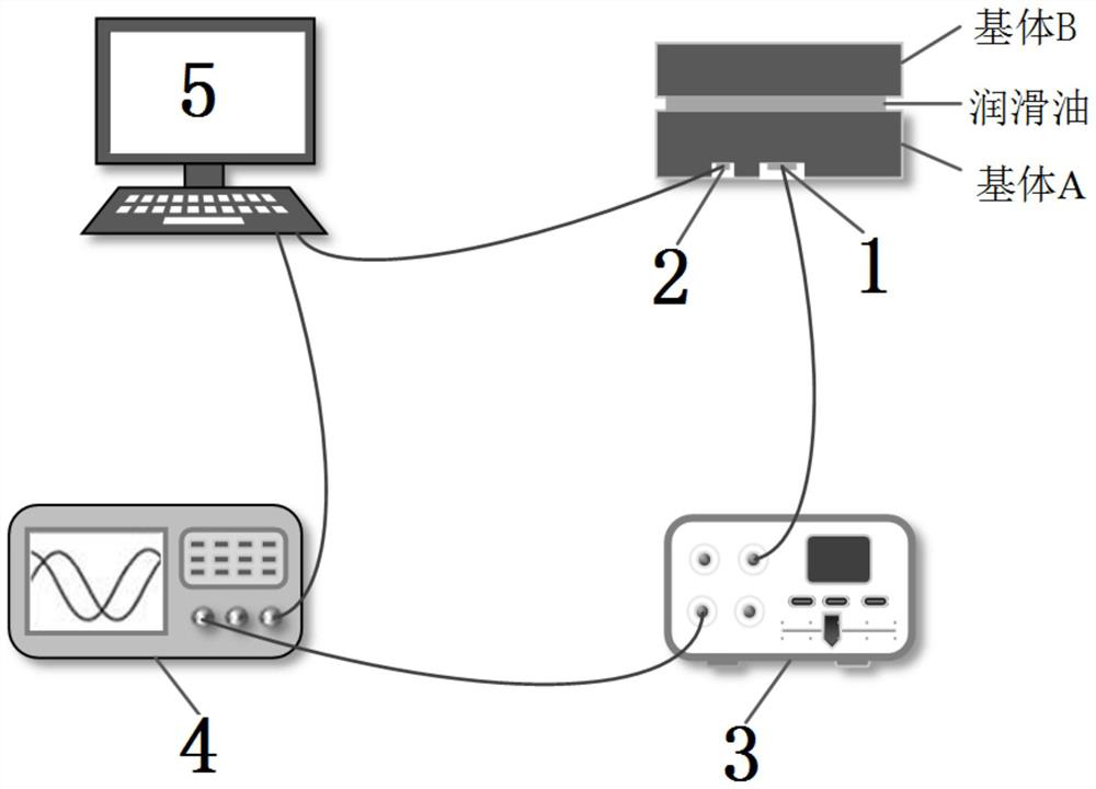
[0034] see figure 1 A reference signal real-time temperature compensation device for ultrasonic measurement of oil film thickness includes an ultrasonic sensor 1, a temperature sensor 2, an ultrasonic pulse transmitter and receiver 3, an oscilloscope 4 and a computer 5, and the ultrasonic pulse transmitter and receiver 3 generates an excitation with adjustable transmission parameters pulse, excite the ultrasonic sensor 1 to generate ultrasonic waves and propagate in the substrate and lubricating oil film, and the ultrasonic reflected signals are received by the ultra...


PUM


Abstract

The invention discloses a reference signal real-time temperature compensation method for ultrasonic measurement of oil film thickness, which calculates the time-shift factor Δt of the reference signal according to the elastic deformation of the matrix A-lubricating oil-matrix B structure and the temperature correlation of sound velocity, and monitors the film thickness During the measurement process, the expansion ratio of the initial wave signal is used to obtain the waveform expansion factor b of the reference signal, and the amplitude attenuation factor a is obtained through the waveform expansion factor b, and then the reference signal at the measured temperature is obtained by compensation of the initial reference signal. The invention does not require complicated calibration work in the early stage, and considers time shift, waveform stretching and amplitude attenuation at the same time, and can fully compensate the reference signal during the measurement process, ensuring accurate calculation of the reflection coefficient amplitude spectrum and phase spectrum, thereby realizing practical engineering. Accurate measurement of lubricating oil film thickness under certain conditions.

Description

technical field [0001] The invention belongs to the technical field of lubricating state detection of friction pairs of machine systems, and in particular relates to a reference signal real-time temperature compensation method for ultrasonic measurement of oil film thickness. Background technique [0002] The friction and wear of parts caused by poor lubrication in production is one of the key reasons for equipment failure, so it is particularly important to monitor the lubrication performance of mechanical equipment. Lubricating oil film thickness is a key parameter to characterize the lubrication performance of mechanical equipment. Different ultrasonic models have been developed for the measurement of lubricating oil film thickness in industrial applications, including time-of-flight method, spring model method, resonance method and phase method. However, these models have not fully considered the influence of temperature. This influence becomes more significant during th...

Claims


Application Information

Patent Timeline
Patent Type & Authority Patents(China)
IPC IPC(8): G01B17/02G01D3/036
CPCG01B17/025G01D3/036
Inventor 武通海贾亚萍窦潘李小芳
Owner XI AN JIAOTONG UNIV
Why Eureka
Try Eureka