

Mooring chain connecting link
a technology of connecting link and chain, which is applied in the direction of driving chain, hoisting equipment, mechanical equipment, etc., can solve the problem that the link cannot accommodate two different sizes of chains
- Summary
- Abstract
- Description
- Claims
- Application Information
AI Technical Summary
Benefits of technology
Problems solved by technology
Method used
Image

Examples
Embodiment Construction
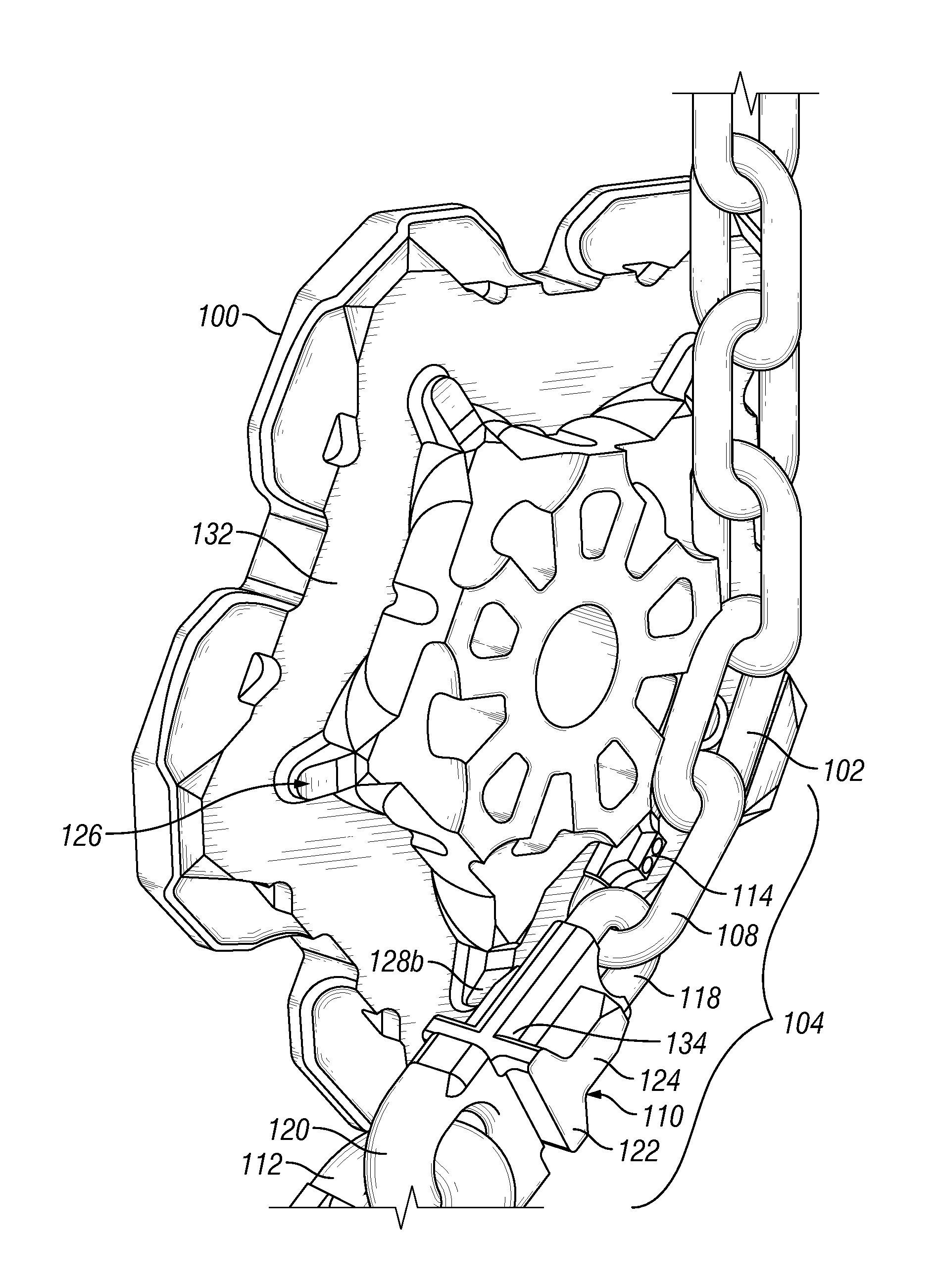
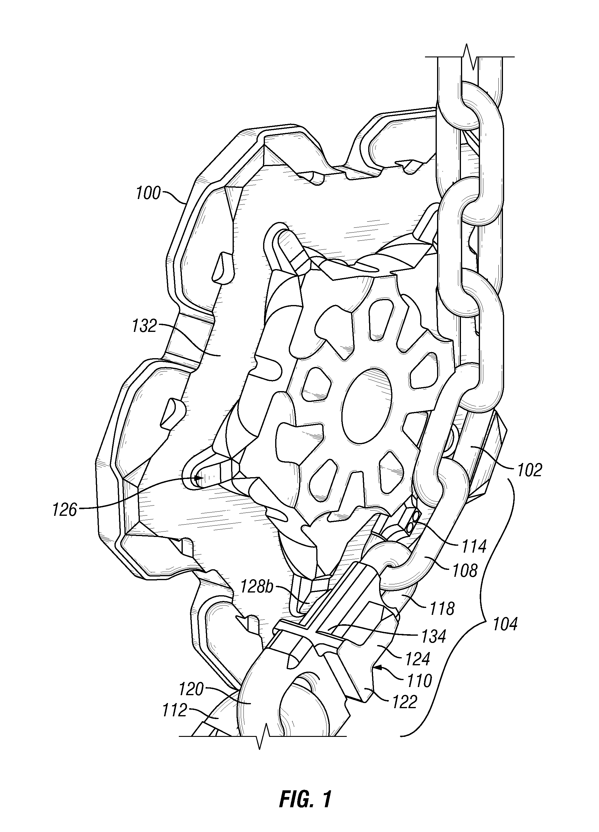
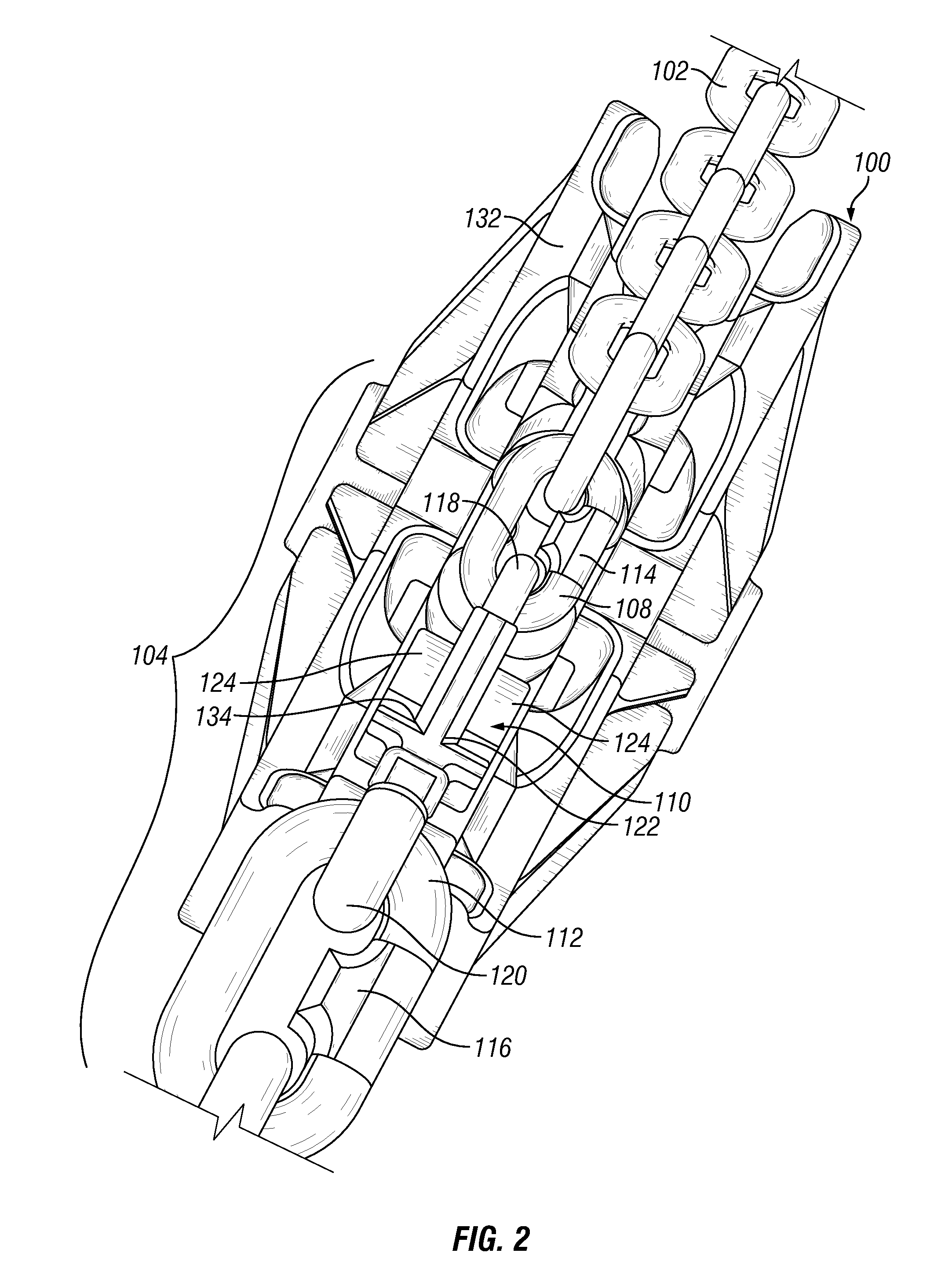
[0013]The connecting link of the present disclosure is generally applicable to many types of chain. In the preferred embodiment, the connecting link of the present disclosure is particularly applicable for connecting heavy-duty chains, such as ships' anchor chains or haulage chains, including chains used in conjunction with chain wheels for transmitting tensional drives.
[0014]Further, the connecting link of the present disclosure can generally be used with many types of chain wheels. In the preferred embodiment, the connecting link of the present disclosure is particularly applicable for use with the embodiments of a dual chain wheel disclosed in U.S. Provisional Application 61 / 555,350, filed on Nov. 3, 2011, the disclosure of which is incorporated herein by reference in its entirety and a copy of which is attached as Exhibit A.
[0015]Certain embodiments of the connecting link of the present disclosure allow two different sized chains to be connected with one another in a manner that...
PUM
 Abstract
Description
Claims
Application Information