Three-dimensional staring spare array photoacoustic imager and methods for calibrating an imager

a spare array and photoacoustic imager technology, applied in the field of photoacoustic apparatus, can solve the problems of elastic expansion and generation of outgoing transient pressure waves, and achieve the effect of widening the viewing angle of the subj

Inactive Publication Date: 2015-09-08
MULTI MAGNETICS
View PDF40 Cites 15 Cited by
  • Summary
  • Abstract
  • Description
  • Claims
  • Application Information

AI Technical Summary

Benefits of technology

The present invention provides an apparatus for photoacoustic imaging of a subject using a sparse array of transducers. This apparatus allows for wider viewing angles and improved image quality compared to previous methods. The digital signals received from the transducers are processed by a computer system to create three-dimensional images of the subject.

Problems solved by technology

These structures undergo a slight but rapid temperature increase, resulting in elastic expansion and generation of an outgoing transient pressure wave.

Method used


Image

  • Three-dimensional staring spare array photoacoustic imager and methods for calibrating an imager
  • Three-dimensional staring spare array photoacoustic imager and methods for calibrating an imager
  • Three-dimensional staring spare array photoacoustic imager and methods for calibrating an imager

Examples


Embodiment Construction

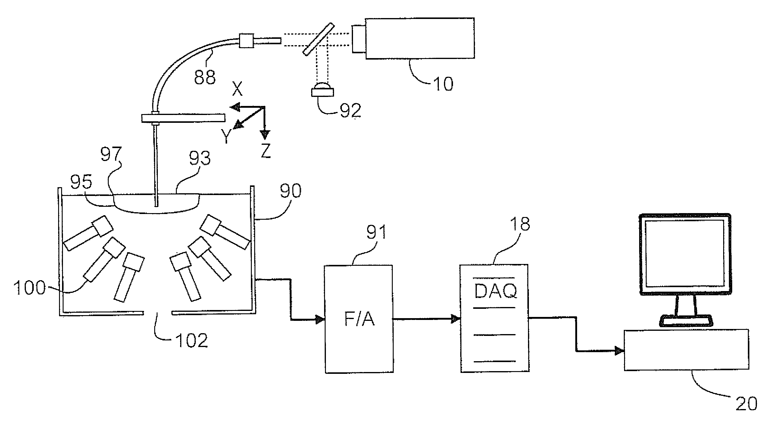
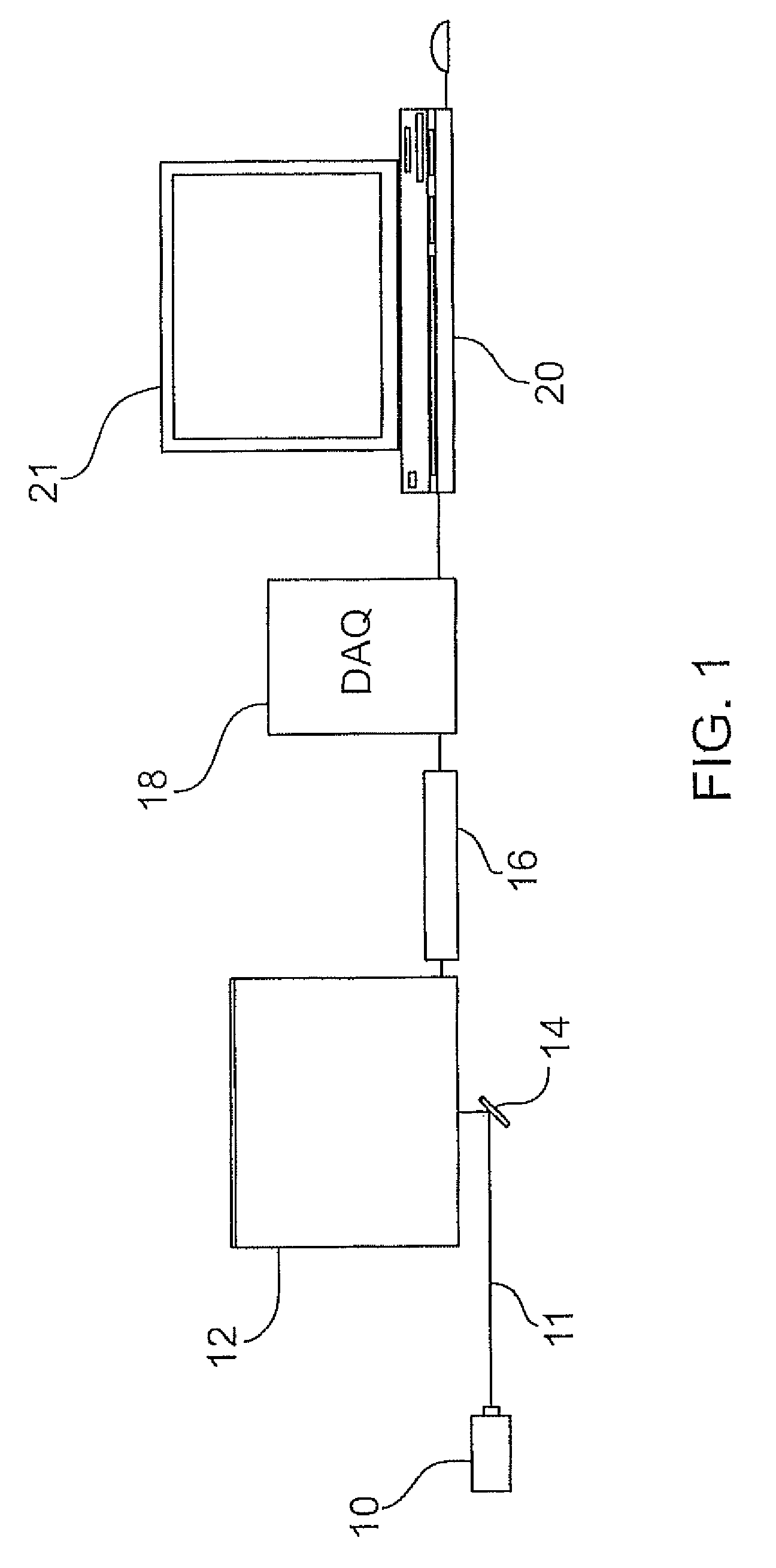
[0059]A schematic overview of a PA imaging apparatus or system according to the present disclosure is shown in FIG. 1. Laser means in the form of laser 10 is provided for producing a suitable laser beam 11 to illuminate a subject, such as a mouse, for medical or scientific imaging in order to generate a photoacoustic signal. In order to reflect the beam 11 into a transducer box 12, the beam is reflected by a mirror 14 which in the illustrated arrangement slopes at a 45 degree angle to a horizontal plane. The beam is then expanded by a lens 15. The beam then passes through the box as shown in FIG. 3 by passing through a clear bottom window 32 which can be circular as shown. A specimen(s) such as a mouse is positioned on top of the box 12 which can provide a table or support surface at 34 for support of the specimen. A suitably sized hole is provided in the top of the box at 36 for passage of the laser beam. The hole 36 is covered with a suitable transparent material 131 such as Mylar...


PUM


Abstract

A photoacoustic imaging apparatus is provided for medical or other imaging applications and also a method for calibrating this apparatus. The apparatus employs a sparse array of transducer elements and a reconstruction algorithm. Spatial calibration maps of the sparse array are used to optimize the reconstruction algorithm. The apparatus includes a laser producing a pulsed laser beam to illuminate a subject for imaging and generate photoacoustic waves. The transducers are fixedly mounted on a holder so as to form the sparse array. A photoacoustic (PA) waves are received by each transducer. The resultant analog signals from each transducer are amplified, filtered, and converted to digital signals in parallel by a data acquisition system which is operatively connected to a computer. The computer receives the digital signals and processes the digital signals by the algorithm based on iterative forward projection and back-projection in order to provide the image.

Description

PRIOR APPLICATIONS[0001]This application is a continuation of International PCT Application No. PCT / CA2008 / 002177 filed Dec. 12, 2008 which claims priority of U.S. Provisional Patent Application No. 61 / 013,127 filed Dec. 12, 2007.BACKGROUND OF THE INVENTION[0002]This invention relates to apparatus for photoacoustic (PA) imaging of structures in an optically absorbing subject and methods and apparatus for calibrating an imaging apparatus of this type. These types of imaging apparatus and methods can be useful for medical, scientific, and industrial imaging, imaging of physiological parameters and tracking of molecular probes.[0003]Photoacoustic (PA) imaging is a method to visualize distribution of optically absorbing objects in a volume of interest. The method employs short laser pulses that illuminate the volume and cause the absorbing objects to heat up slightly and undergo thermoelastic expansion which results in outward-propagating pressure waves. By measuring the time-of-flight ...

Claims


Application Information

Patent Timeline
Patent Type & Authority Patents(United States)
IPC IPC(8): A61B5/05G01N29/06G01N29/30A61B5/00G01N29/24G06F19/00A61B8/08
CPCG01N29/2418A61B5/0059A61B5/0095G01N29/0654G01N29/30A61B8/483G01N2291/106
Inventor CARSON, JEFFREY J. L.EPHRAT, PINHASKEENLISIDE, LYNNROUMELIOTIS, MICHAEL BARRET
Owner MULTI MAGNETICS
Why Eureka
Try Eureka