Multiple suction cup attachment platform: securing an electronic device on a vertical surface

a technology of vertical surface and attachment platform, which is applied in the direction of stands/trestles, instruments, vehicle components, etc., can solve the problems of small devices, lack of multi-purpose apparatus that may serve as an attachment system, etc., and achieve the effect of convenient insertion, sufficient tension and flexible us

Inactive Publication Date: 2015-09-08
JOHNSON AUGUST A
View PDF3 Cites 27 Cited by
  • Summary
  • Abstract
  • Description
  • Claims
  • Application Information

AI Technical Summary

Benefits of technology

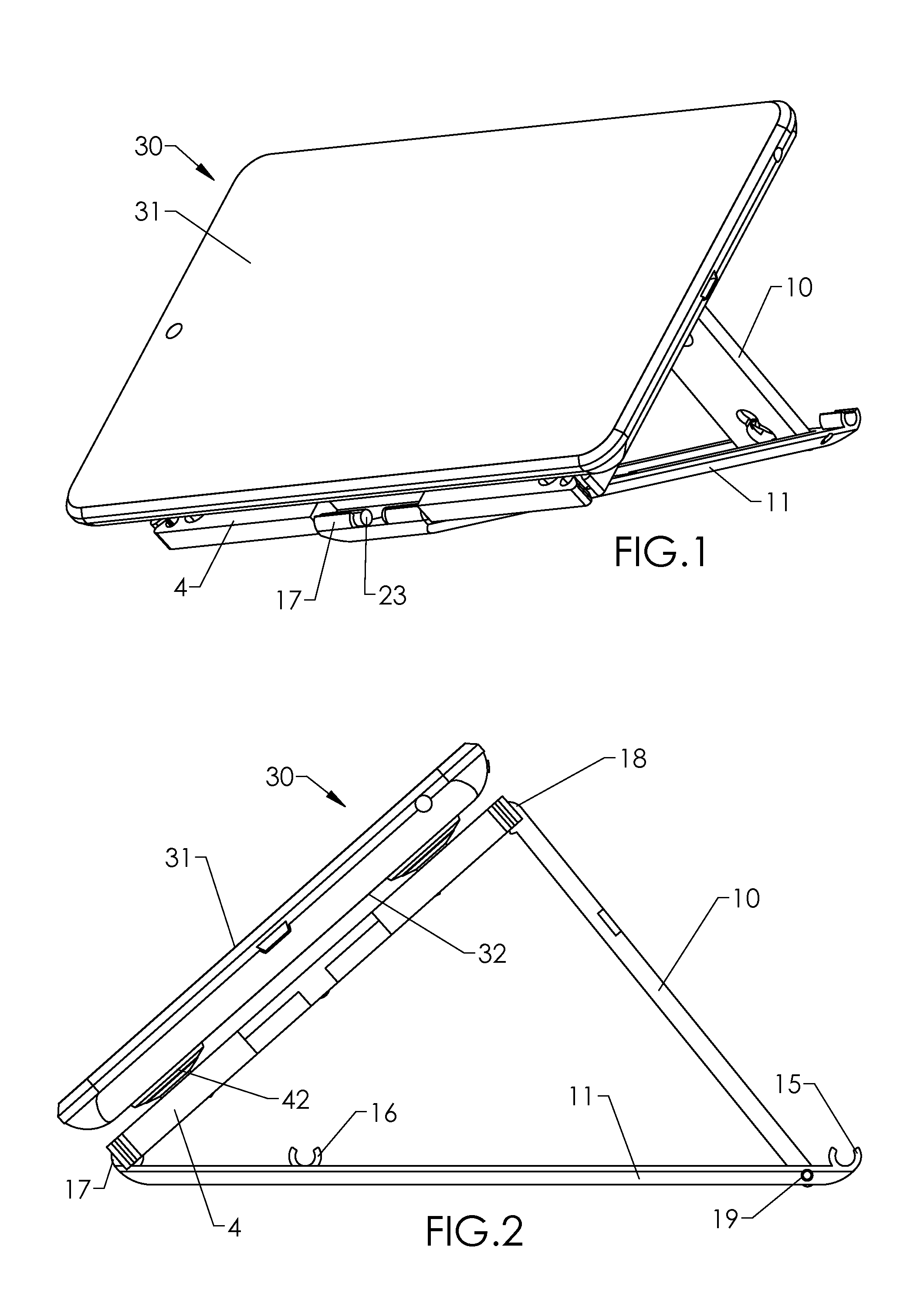
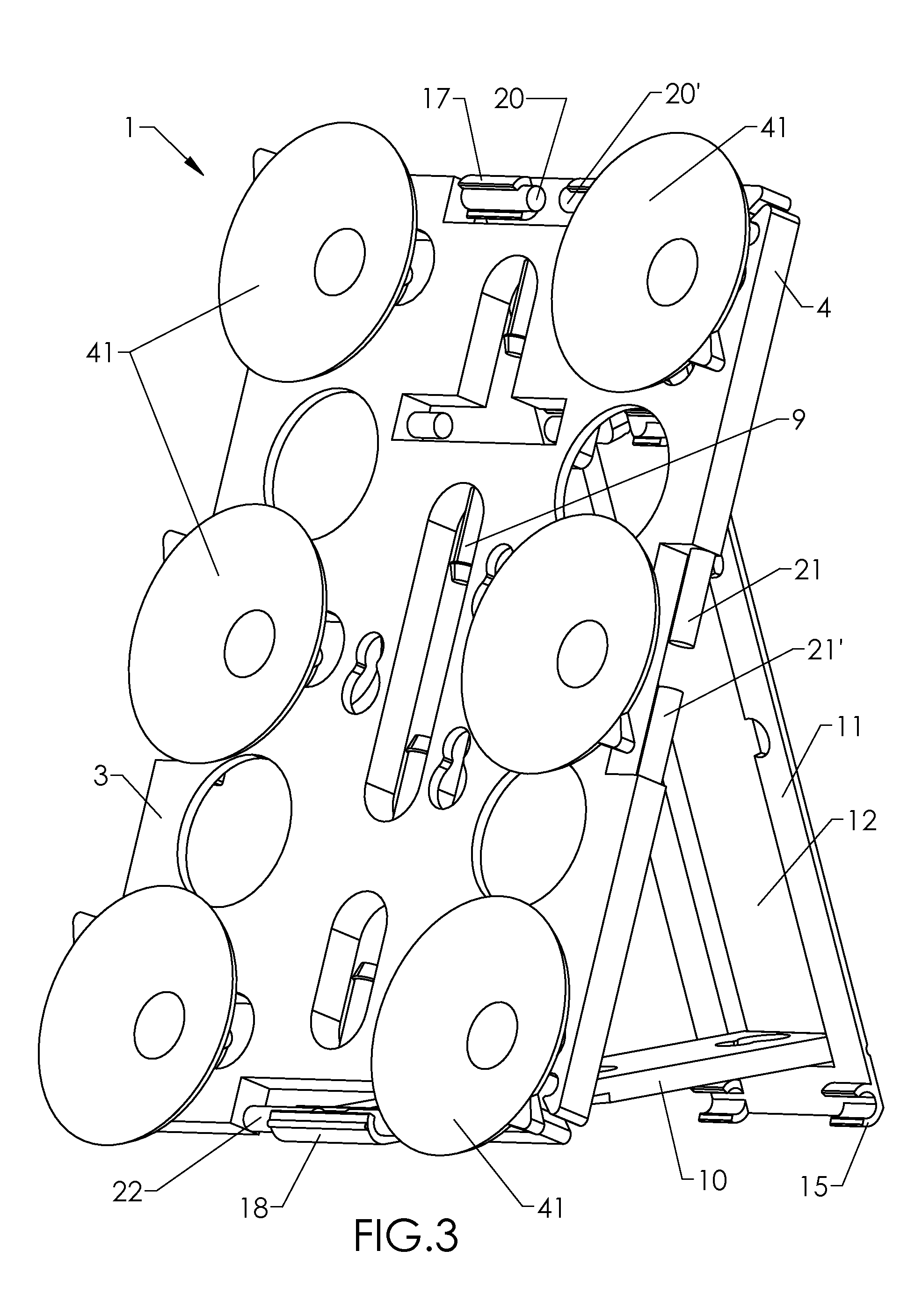
[0012]The kickstand has been designed to allow for independent functions besides the attachable kickstand function simply. The kickstand is designed with slots at which to attach extra suction cups while not in use. The design allows the kickstand to be snapped onto the platform at four different locations. The kickstand is designed in a triangular shape with three different angles which then allows for varying view angles when implementing the kickstand for use. This attachable / detachable design provides flexibility in use with the platform. The kickstand is created of two component parts, which are attached by a metal pin, allowing for rotation of the central kickstand arm around a central axis, allowing varying angles. The adjustable legs of the kickstand contain snap openings at each end, allowing the kickstand to be snapped onto the larger platform mechanism, either while is use as a kickstand, or in a folded position for storage purposes while not in use at the rear of the platform. These slot openings will be referred to as snap slot openings associated with the kickstand, or alternative attachments. The platform is purposefully designed to allow the kickstand to be attached at the rear for storage purposes, but still retain the functionality of attached suction cups at the rear of the platform to allow for attachment to a smooth surface.
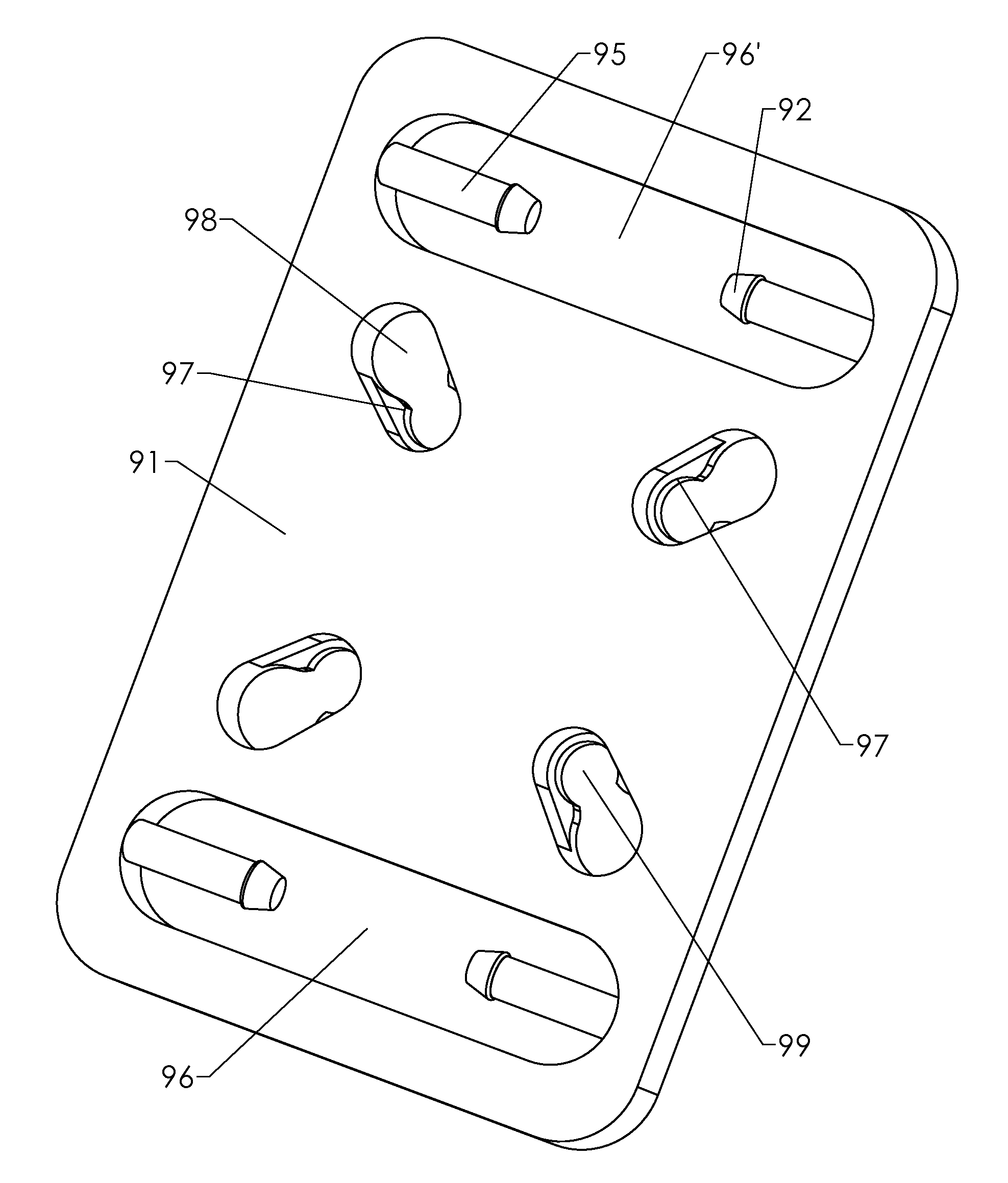
[0013]The four kickstand snap slot openings and round peg / post arms integrated into the platform design provide additional functionality above and beyond use of the kickstand simply. These four snap slots are aligned to be directly opposite each other, with one slot on each of the four sides of the platform mount. These snap slot openings and post arms are also designed to be used with properly sized elastic straps, 1 to 1.5 inches in width that can be easily inserted into the slots. The connections (also called “insertion points” due to loops of the strap being inserted between arms of their respective arm-systems) between the mounting plate and the ends of the elastic strap are designed to be strong to allow sufficient tension on the straps to provide a secure attachment around an object.
[0015]The elastic strap would incorporate a Velcro material which could then attach to the opposing strap, or strap around an object to allow the platform to be secured for use on alternative surfaces or objects other than something that is smooth. The In certain embodiments, the retention strap fastens in a tightened configuration by means of patch(es) of hook / loop fastener. The strap's elasticity, and the leeway in connection location provided by hook / loop fastener, allows the user to tighten the retention strap around / against an object to hold the platform securely in place on / against said object. The retention strap may connect to one portion of the mounting plate, and loop through the slot at the opposing side of the plate to form a space between the strap and the mount for receiving the object. After looping through said another slot opening, the retention strap may attach to itself in the tightened configuration for capturing the object. Alternatively, other fasteners and fastener locations for latching / securing the retention strap in a tightened configuration may be used, for example, hook-and-loop cooperating patches at other locations on the strap, or fastener(s) on the mounting plate that cooperate with a fastener(s) on the retention strap.
[0019]Alternatively, the size of the platform can be modified, altered, or varied to accommodate the specific class of devices. For example, a smaller, less preferred version of the platform card can be created with multiple suction cup slots, however would not include the kickstand clipping slots or the cord slots. This modified design would therefore only work with smaller devices. In the following drawings, two differently sized platform versions are presented for demonstration purposes, which we have classified as “small” and “large”. The present invention is not limited to a specific platform size or design, but rather a platform that incorporates one or more of the unique design features. This could include a combination of the previously outlined design features and is therefore not limited to a concept design that only incorporates all of them onto one platform design. As such, the invention allows for tremendous flexibility in platform size, integrated features, and relative functionality. In the following drawings two versions of the invention are presented, one of which incorporates all of the identified design features, and one with only the suction cup slot design features.

Problems solved by technology

Still, there is an absence of a multi-purpose apparatus that may serve as an attachment system that is operable with nearly all photo-capable cellular / smartphone designs as well as tablets and e-readers.
This modified design would therefore only work with smaller devices.

Method used


Image

  • Multiple suction cup attachment platform: securing an electronic device on a vertical surface
  • Multiple suction cup attachment platform: securing an electronic device on a vertical surface
  • Multiple suction cup attachment platform: securing an electronic device on a vertical surface

Examples


Embodiment Construction

[0051]Referring to the figures, there are shown several, but not the only, embodiments of a mounting apparatus for securing an electronic device that preferably contains photo and video recording capabilities for capturing hands free pictures and video, or alternatively for suspending a device for hands free screen viewing in a variety of configurations. The preferred embodiment comprises a rigid platform mount with multiple suction cup attachment options, providing a broad array of combinations of suction cups, but other features may be included in certain embodiments of the invention. These additional features include an attachable kickstand, cording slots, screw hole slots, strap attachment arms / slots, all of which provide for enhanced functionality of the rigid platform, but are not all required to accomplish the primary task of suspending an electronic device from a smooth vertical surface. While the preferred embodiment would include all of the integrated design features, some...


PUM


Abstract

A mounting apparatus permits easy and quick attachment and removal of the apparatus securing a portable device to smooth surfaces, or objects. An injection molded platform which allows multiple suction cups to be attached to secure a portable electronic device such as a smart phone, cellular phone, tablet, e-reader, or other digital media device to a smooth surface, or object. The primary platform is an injection molded part specifically designed to accommodate the insertion of mini suction cups, small suction cups, and medium suction cups. The injection molded platform contains multiple openings specifically designed to allow the attachment of an array of suction cups, and alternative mechanisms including kickstand assembly, elastic straps or cording. It is a further object of the invention to provide a platform apparatus that can be attached to smooth surfaces for different sized devices with touch screen capabilities, and devices with camera and video functions.

Description

[0001]This application claims benefit of Provisional Application Ser. No. 61 / 701,049, filed Sep. 14, 2012 and entitled “Multiple Suction Cup Attachment Platform; Securing an electronic device on a vertical surface”, the disclosure of which is incorporated by this reference.BACKGROUND OF THE INVENTION[0002]1. Field of the Invention[0003]The present invention generally relates to a mounting accessory for electronic devices that have photo and video-recording capabilities. More specifically, the preferred embodiment is a mounting apparatus, for holding a portable electronic device, such as a cellular phone, smart phone, tablet, camera, e-reader, or other digital media devices, whereby the digital device may be connected to a surface or object preferably via suction cups, for hands-free use of the digital device. The invention relates to an apparatus that securely holds a portable electronic device on a smooth surface, vertical or horizontal. More particularly, the invention relates to ...

Claims


Application Information

Patent Timeline
Patent Type & Authority Patents(United States)
IPC IPC(8): G06F1/16B60R11/00F16M11/00
CPCG06F1/1626B60R11/00F16M11/00B60R2011/0056B60R2011/0068F16M11/041F16M11/10F16M11/105F16M13/00F16M13/022
Inventor JOHNSON, AUGUST A.
Owner JOHNSON AUGUST A
Why Eureka
Try Eureka