
Roping training device

a training device and rope technology, applied in the field of rope training devices, can solve the problems of not being able to accommodate the user's shifting position relative to the camera, the system does not disclose a system, and the technique is not easy to observe. , to achieve the effect of superior training and facilitation of observation of one's techniqu

Inactive Publication Date: 2015-09-08
PAYNE ERIC
View PDF25 Cites 5 Cited by
  • Summary
  • Abstract
  • Description
  • Claims
  • Application Information

AI Technical Summary

Benefits of technology

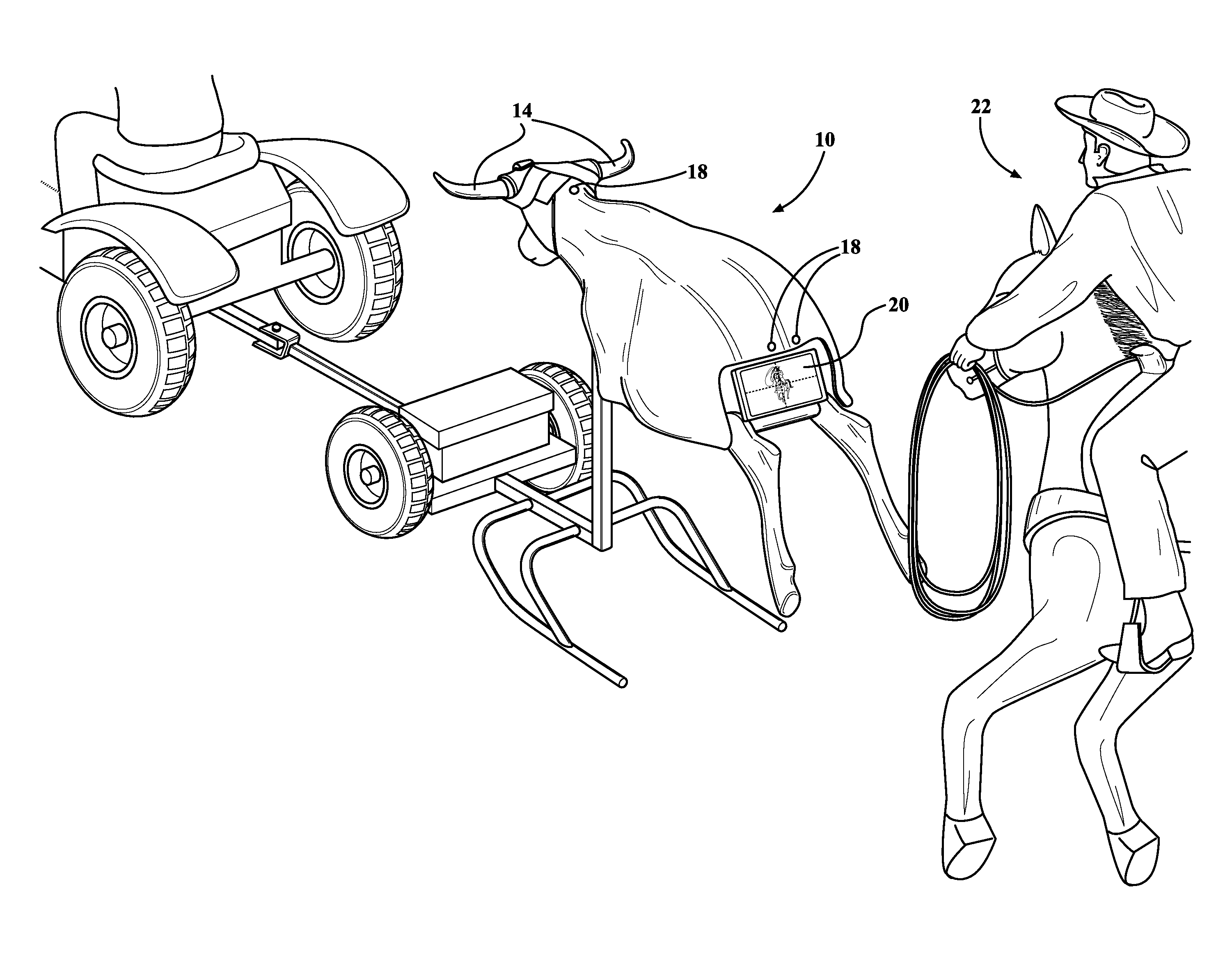
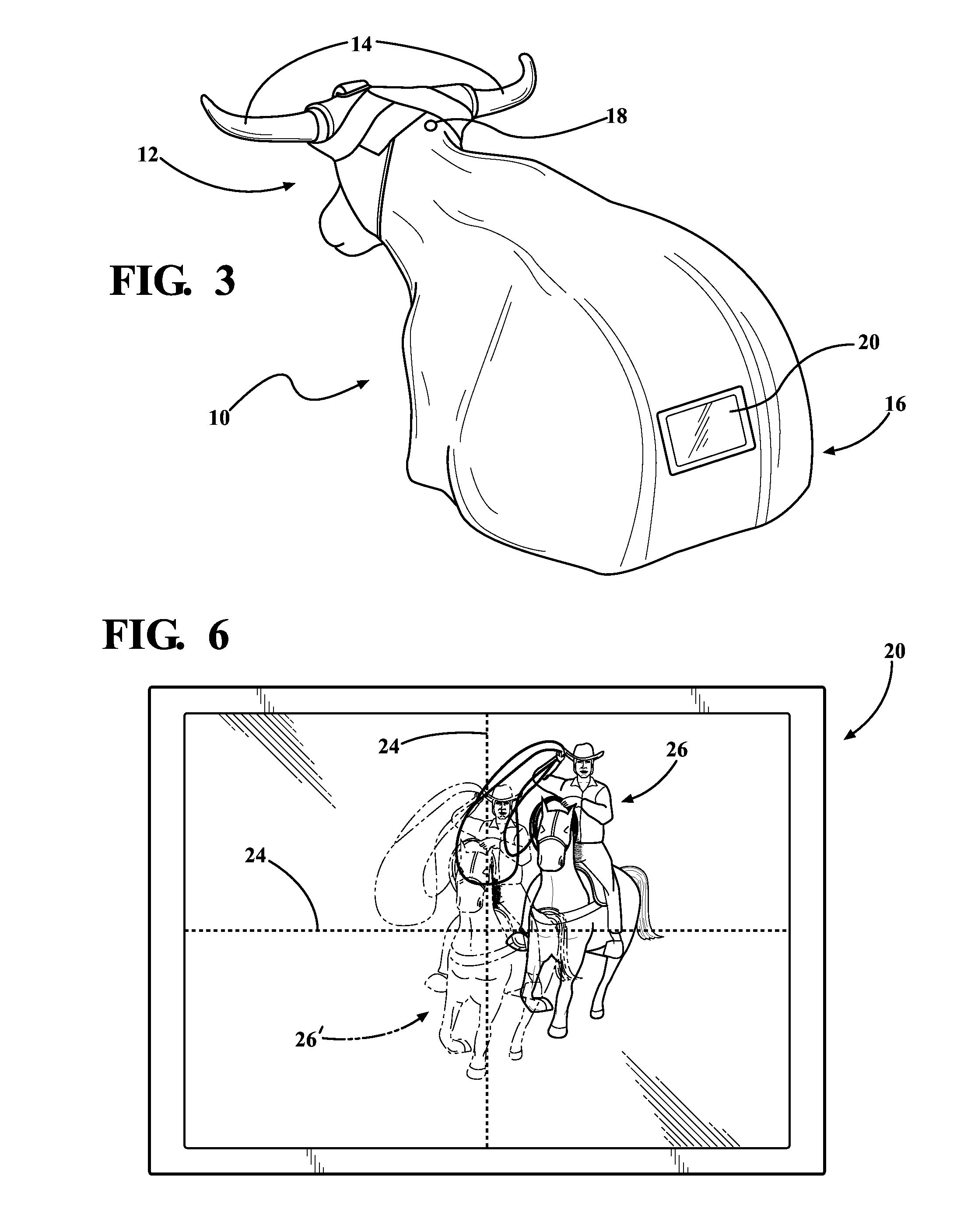
[0010]A roping training apparatus is provided for facilitating placement of a remote roper with respect to a roping dummy, which can be stationary or mobile. A dummy body has a head portion, a rear portion, and a lasso target, such as the animal's head, horns, or legs. A sensor is disposed on the dummy to ascertain the roper's position relative to the target area. The position sensor may include a radar system, a video camera, or a combination of both types of sensors. In one embodiment, the position sensor comprises a video camera mounted between the horns at the back of the dummy's head, with the camera pointed rearward. In one embodiment, a monitor is mounted in the rear portion of the dummy easily visible to the roper situated behind the dummy as in a typical roping situation, thereby minimizing interference with the roper's focus and technique. The monitor is operatively connected to the position sensor(s) and displays the roper's real-time placement relative to the target, as well as a helpful real-time view of the roper's throwing technique. The feedback monitor also displays a positional reference corresponding to a preferred roper placement. By displaying the roper's actual position simultaneously with a preferred roper position, combined with the helpful perspective view of his throwing attempts, the roper is able to easily and quickly change his position relative to the dummy and the target area, as well as modify his technique, thereby facilitating a successful capture of the head, horns, or other portion of the dummy's body.
[0013]Other embodiments of the invention include a recording device to record the data generated by a roper's ensnarement attempts and successes at various placement points relative to the target, and configuring a microprocessor to process and / or modify the positional reference data displayed on the monitor. This could be especially valuable, for example, to play back a recording of one or more throwing attempts and successes, to better identify defects in the thrower's technique. Incorporating a microprocessor also enables the system to modify the positional reference and preferred roper placement based not only on input provided by the user, but also based on analysis of a roper's history of roping attempts and successes at a variety of placement locations. For example, if a roper achieves a higher ensnarement rate when he is 15 feet away and 20 degrees off center versus 15 feet away and 10 degrees off center, the system may be programmed to shift the positional reference displayed on the monitor to a new preferred placement corresponding to the placement where that roper has more consistent success.
[0015]The present invention provides a superior means of training to successfully rope calves and steers by facilitating proper roper placement relative to the target and by facilitating observation of one's technique, both in real time and after one or more attempts. The invention is also adaptable for use in conjunction with existing roping dummy models without extensive modifications.

Problems solved by technology

None of these patents, however, disclose a system to measure a user's position relative to the dummy and to provide information concerning the roper's displacement, if any, from a preferred roper position.
However, none of these systems disclose a camera or other user position sensory device that is disposed on a target at which a remote user is aiming.
None of these systems accommodate a user shifting his / her position relative to the camera, or relative to a remote target.

Method used


Image

  • Roping training device
  • Roping training device
  • Roping training device

Examples


Embodiment Construction

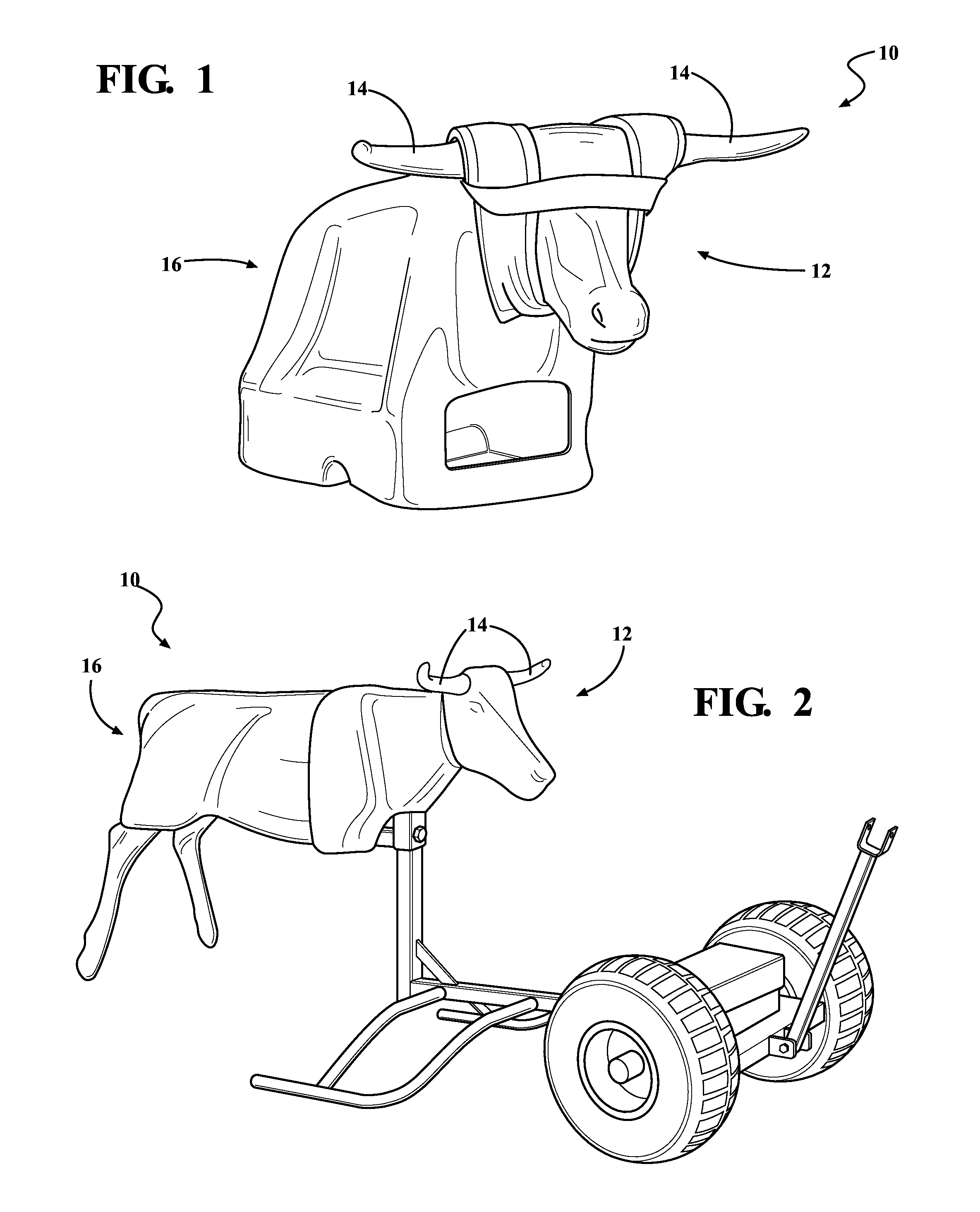
[0025]Referring to FIG. 1, a stationary dummy 10 is shown having a front portion 12, horns 14 and rear portion 16. As shown in the figure, different sizes of horns 14 may be attached to the calf roping dummy 10 according to a desired age and species of steer, with calves having no horns and young animals having shorter horns, for example. FIG. 2 shows a roping dummy 10 designed for mobile application, again having front portion 12, horns 14 and rear portion 16. Such dummies are commercially available from the Heel-O-Matic company, Longmont, Colo.

[0026]FIG. 3 shows a stationary steer roping dummy 10 having front portion 12, horns 14 and rear portion 16. Also shown is a position sensor 18 mounted at the back of the dummy's head between horns 14. Position sensor 18 may be a video camera aimed rearward to capture images of a roper on foot in position to throw a rope over a target, such as the head or horns 14. Position sensor 18 could also incorporate a radar system comprising a radar t...


PUM


Abstract

A roping training dummy is claimed comprising a dummy representing an animal having a target to be lassoed by a roper. A position sensor, such as video camera or radar system, is disposed on the dummy for monitoring the real-time position of the roper relative to the lasso target. A monitor on the dummy is visible to the roper and operatively connected to the position sensor. The monitor displays the roper's real-time position and a positional reference corresponding to a preferred roper placement.

Description

BACKGROUND OF THE INVENTION[0001]1. Field of the Invention[0002]Rodeos have grown in popularity. In particular, competitive roping has attracted a growing number of spectators and participants. The sport entails an individual or team throwing a rope, or lasso, to ensnare a calf or steer. The animal may be ensnared by the head, horns, or leg(s). In order to improve their success rate, ropers must practice their roping skills. Practicing on live calves and steers, however, is frequently inconvenient, expensive, or otherwise impractical. As a result, both amateur and professional rodeo ropers frequently employ roping dummies to practice their skills. These roping dummies superficially resemble a calf or steer, with the head, horns, and / or legs configured to be ensnared by a lasso. The dummy can be stationary or mobile, with the latter configured to be pulled by a motor vehicle. Roping dummies are available from a variety of manufacturers, including Heel-O-Matic, whose information is ac...

Claims


Application Information

Patent Timeline
Patent Type & Authority Patents(United States)
IPC IPC(8): A01K15/02G09B19/00
CPCG09B19/003
Inventor PAYNE, ERIC
Owner PAYNE ERIC
Learn More