Audio signal decoder, audio signal encoder, methods and computer program using a sampling rate dependent time-warp contour encoding

a time-warp contour and encoder technology, applied in the field of audio signal decoders, can solve problems such as reducing coding efficiency, and achieve the effects of increasing the coding efficiency of time-warp values, high coding efficiency, and keeping the computational complexity small

Active Publication Date: 2015-09-08
FRAUNHOFER GESELLSCHAFT ZUR FOERDERUNG DER ANGEWANDTEN FORSCHUNG EV +1
View PDF19 Cites 25 Cited by
  • Summary
  • Abstract
  • Description
  • Claims
  • Application Information

AI Technical Summary

Benefits of technology

[0019]This embodiment according to the invention is based on the finding that a time warp (which is, for example, described by a time warp contour) can be efficiently encoded if the mapping rule for mapping codewords of the encoded time warp information onto decoded time warp values is adapted to the sampling rate because it has been found that it is desirable to represent a larger time warp per sample for lower sampling frequencies than for higher sampling frequencies. It has been found that this desire arises from the fact that it is advantageous if a time warp per time unit, which is representable by the set of codewords of the encoded time warp information, is approximately independent from the sampling frequency, which translates into the consequence that a time warp representable by a given set of codewords should be larger for smaller sampling frequencies than for higher sampling frequencies under the assumption that the number of time warp codewords per audio sample (or per audio frame) remains at least approximately constant independent from the actual sampling frequency.
[0032]In an embodiment, the time warp calculator is configured to compute supporting points of a time warp contour on the basis of the decoded time warp values. In this case, the time warp calculator is configured to interpolate between the supporting points to obtain the time warp contour as the decoded time warp information. In this case, a number of decoded time warp values per audio frame is predetermined and independent from the sampling frequency. Accordingly, the interpolation scheme between the supporting points may be left unchanged, which helps to keep the computational complexity small.

Problems solved by technology

For signals with varying pitch, however, the energy corresponding to each harmonic component is spread over several transform coefficients, thus leading to a reduction of coding efficiency.

Method used


Image

  • Audio signal decoder, audio signal encoder, methods and computer program using a sampling rate dependent time-warp contour encoding
  • Audio signal decoder, audio signal encoder, methods and computer program using a sampling rate dependent time-warp contour encoding
  • Audio signal decoder, audio signal encoder, methods and computer program using a sampling rate dependent time-warp contour encoding

Examples


Embodiment Construction

1. Time Warp Audio Signal Encoder According to FIG. 1

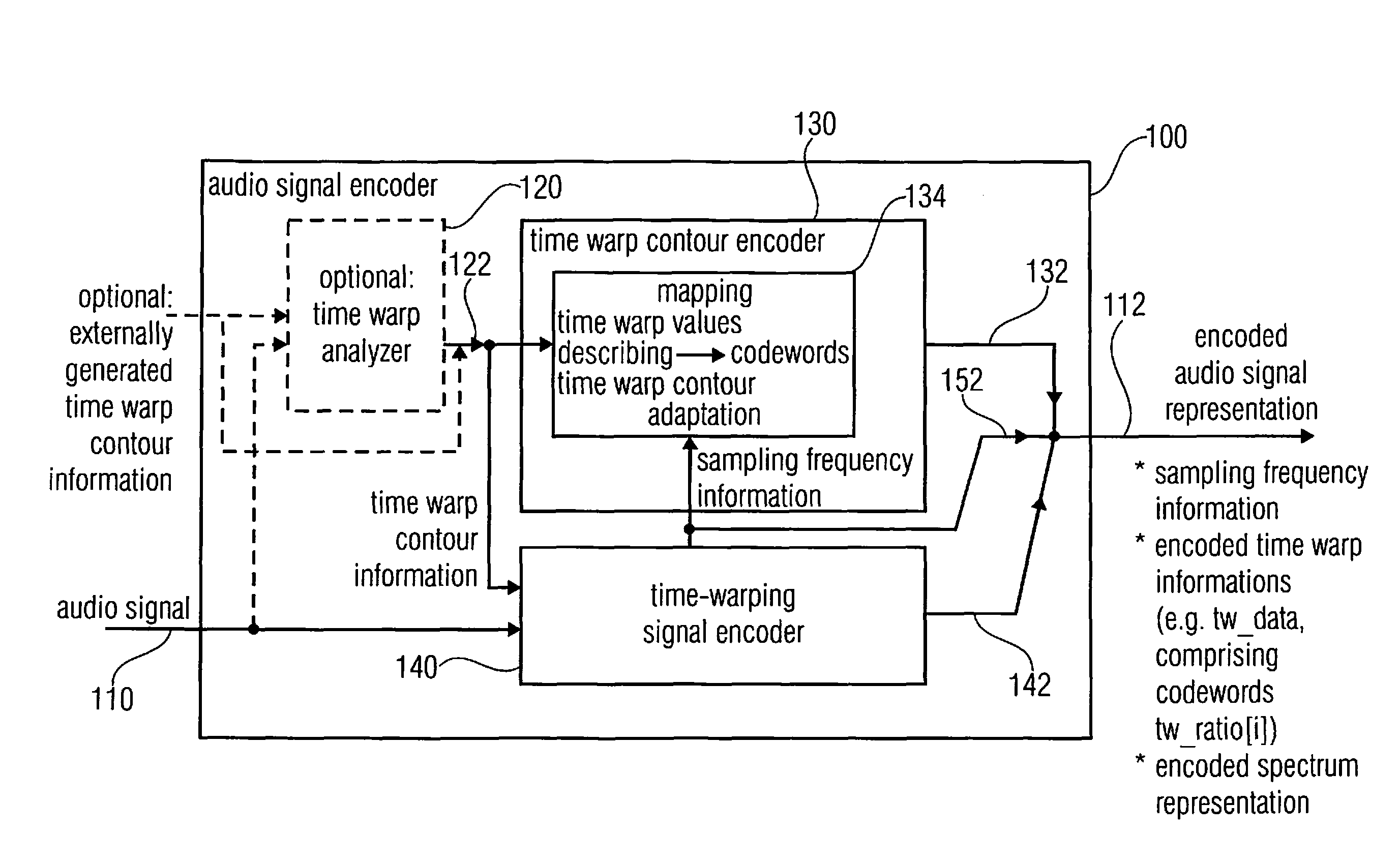
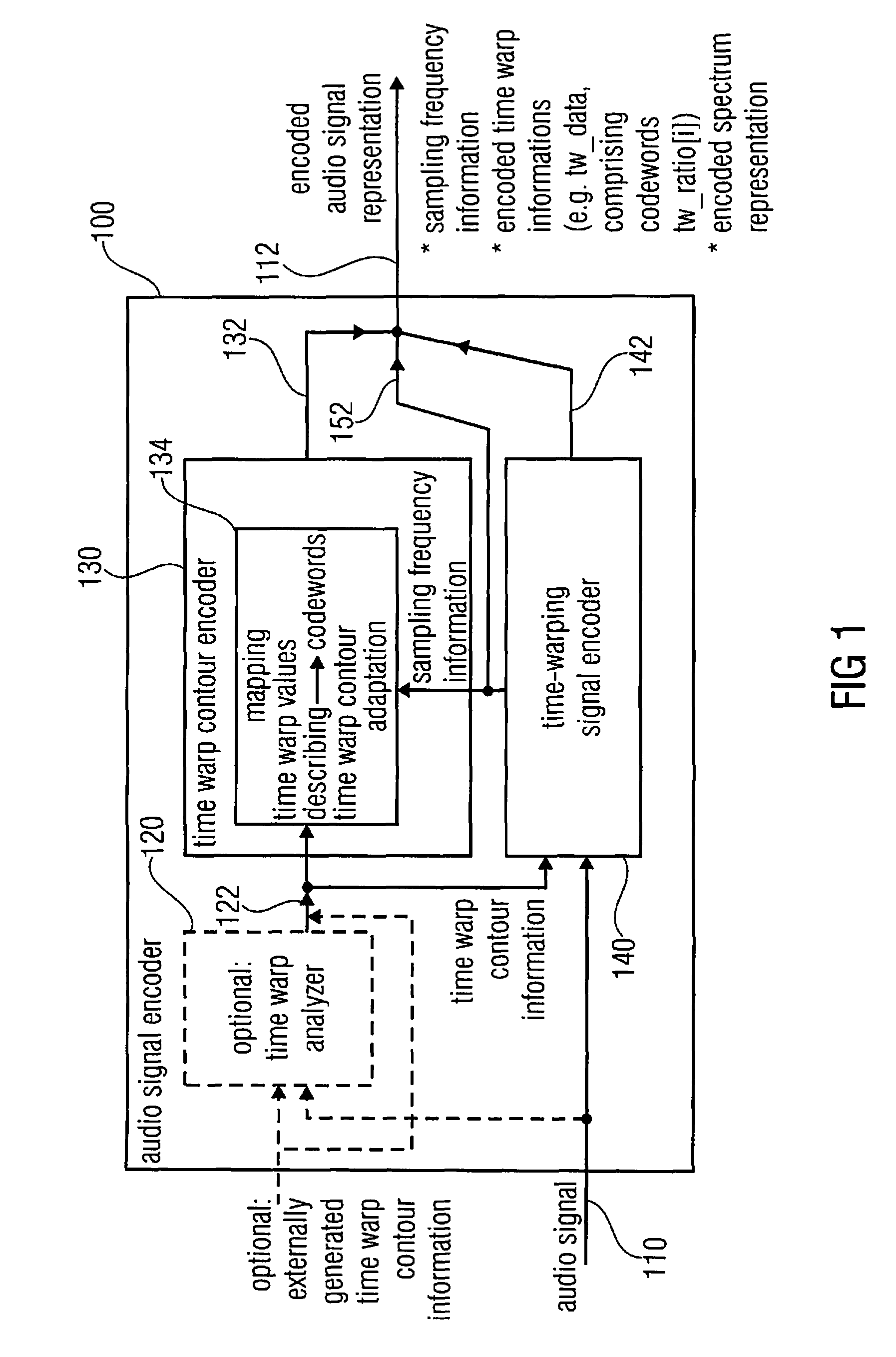
[0062]FIG. 1 shows a block schematic diagram of a time warp audio signal encoder 100 according to an embodiment of the invention.

[0063]The audio signal encoder 100 is configured to receive an input audio signal 110 and, to provide, on the basis thereof, an encoded representation 112 of the input audio signal 110. The encoded representation 112 of the input audio signal 110 comprises, for example, an encoded spectrum representation, an encoded time warp information (which may be designated, for example, with “tw_data”, and which may, for example, comprise codewords tw_ratio[i]) and a sampling frequency information.

[0064]The audio signal encoder may optionally comprise a time warp analyzer 120, which may be configured to receive the input audio signal 110, to analyze the input audio signal and to provide a time warp contour information 122, such that the time warp contour information 122 describes, for example, a temporal evolution ...


PUM


Abstract

An audio signal decoder configured to provide a decoded audio signal representation on the basis of an encoded audio signal representation including a sampling frequency information, an encoded time warp information and an encoded spectrum representation includes a time warp calculator and a warp decoder. The time warp calculator is configured to adapt a mapping rule for mapping codewords of the encoded time warp information onto decoded time warp values describing the decoded time warp information in dependence on the sampling frequency information. The warp decoder is configured to provide the decoded audio signal representation on the basis of the encoded spectrum representation and in dependence on the decoded time warp information.

Description

CROSS-REFERENCE TO RELATED APPLICATIONS[0001]This application is a continuation of copending International Application No. PCT / EP2011 / 053538, filed Mar. 9, 2011, which is incorporated herein by reference in its entirety, and additionally claims priority from U.S. Application No. 61 / 312,503, filed Mar. 10, 2010, which is also incorporated herein by reference in its entirety.BACKGROUND OF THE INVENTION[0002]Embodiments according to the invention are related to an audio signal decoder. Further embodiments according to the invention are related to an audio signal encoder. Further embodiments according to the invention are related to a method for decoding an audio signal, to a method for encoding an audio signal and to a computer program.[0003]Some embodiments according to the invention are related to a sampling frequency dependent pitch variation quantization.[0004]In the following, a brief introduction will be given into the field of time-warped audio encoding, concepts of which can be...

Claims


Application Information

Patent Timeline
Patent Type & Authority Patents(United States)
IPC IPC(8): G10L19/00G10L19/022G10L25/90G10L19/02
CPCG10L19/022G10L19/0212G10L25/90G10L19/02G10L21/04
Inventor BAYER, STEFANBAECKSTROEM, TOMGEIGER, RALFEDLER, BERNDDISCH, SASCHAVILLEMOES, LARS
Owner FRAUNHOFER GESELLSCHAFT ZUR FOERDERUNG DER ANGEWANDTEN FORSCHUNG EV
Why Eureka
Try Eureka