
Refueling boom control system

a control system and refueling boom technology, applied in the field of aircraft, can solve the problems of not being able to control the refueling boom as easily in another type of tanker aircraft, not being able to intuitively understand the input control of a less-experienced boom operator, and more training and expense than desired

Active Publication Date: 2015-09-15
THE BOEING CO
View PDF9 Cites 6 Cited by
  • Summary
  • Abstract
  • Description
  • Claims
  • Application Information

AI Technical Summary

Benefits of technology

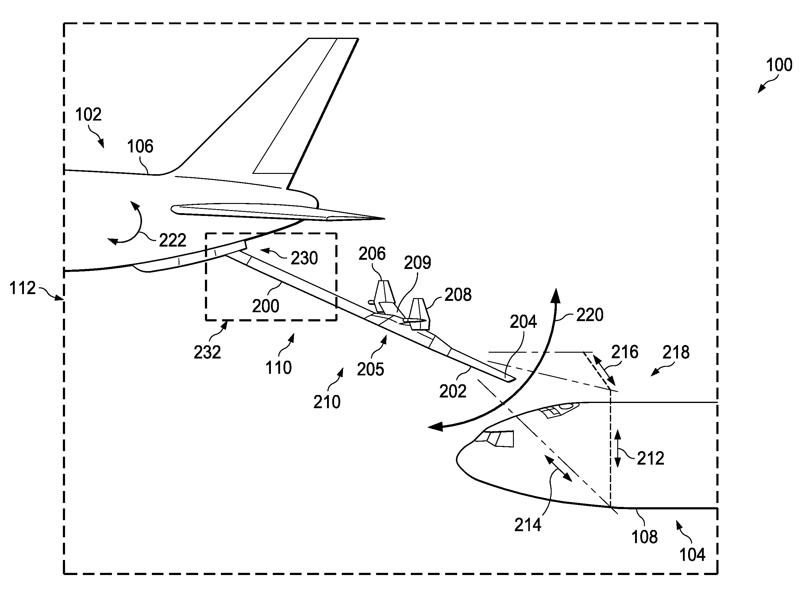
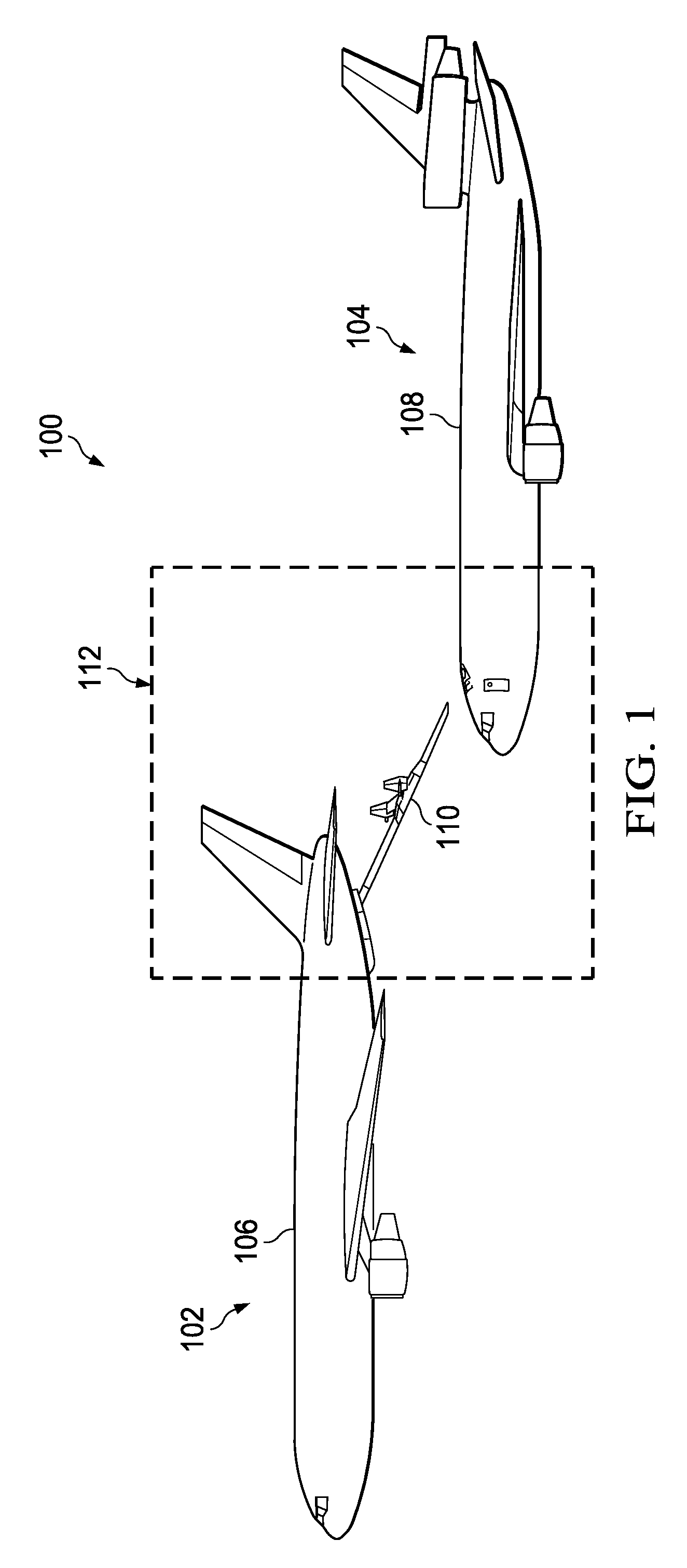
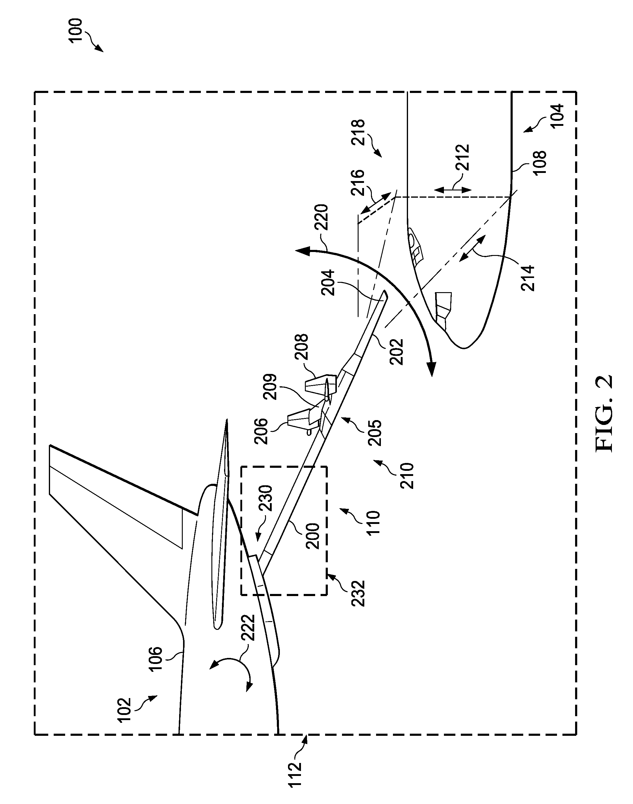
This patent describes an apparatus and method for controlling the movement of a refueling boom on a tanker aircraft. The refueling controller receives operator commands for moving the boom in a desired direction, which can include both azimuth movement and elevation movement. The controller generates intermediate commands to achieve the desired movement, which can include roll movements and pitch movements. The technical effect of this invention is the ability to accurately and efficiently control the movement of a refueling boom in a tanker aircraft during flight. This can improve operational efficiency and safety during refueling operations.

Problems solved by technology

As a result, an operator that is trained and experienced with refueling operations in one type of tanker aircraft may not be able to control the refueling boom as easily in another type of tanker aircraft.
This type of input control may be more complicated than desired and may not be as intuitive to a less-experienced boom operator.
This difference in the controls for performing refueling operations may result in more training and expense than desired.
Further, if the different operators are not familiar with all the different types of tanker aircraft used, then the operators prepared for performing missions on a particular type of aircraft may not be available as desired.

Method used


Image

  • Refueling boom control system
  • Refueling boom control system
  • Refueling boom control system

Examples


Embodiment Construction

[0033]The different illustrative embodiments recognize and take into account one or more considerations. For example, the illustrative embodiments recognize and take into account that the differences in the controls used to control a refueling boom may increase the difficulty in performing refueling operations with different types of tanker aircraft. Further, the illustrative embodiments recognize and take into account that one control that may be different between different types of tanker aircraft is the manner in which a refueling boom moves in response to a movement of a control stick.

[0034]The illustrative embodiments also recognize and take into account that if the operator moves the control stick in one direction, the refueling boom may not always move in the direction that corresponds to the movement of the control stick. For example, the operator may move the control stick to the left. The operator may expect that the refueling boom will move an azimuth direction in the ref...


PUM


Abstract

A method and apparatus comprising a refueling controller. The refueling controller is configured to receive a number of operator commands for moving a refueling boom on a tanker aircraft in a desired direction. The number of operator commands defines at least one of an azimuth movement and an elevation movement of the refueling boom during flight of the tanker aircraft. The refueling controller is further configured to generate a number of intermediate commands for moving the refueling boom in the desired direction as defined by the number of operator commands. The number of intermediate commands defines at least one of a roll movement and a pitch movement such that the refueling boom moves in the desired direction.

Description

BACKGROUND INFORMATION[0001]1. Field[0002]The present disclosure relates generally to aircraft and, in particular, to refueling aircraft. Still more particularly, the present disclosure relates to a method and apparatus for managing movement of a refueling boom for a refueling aircraft.[0003]2. Background[0004]Aerial refueling is the process of transferring fuel from one aircraft to another aircraft during flight. The aircraft from which the fuel originates is referred to as a tanker aircraft. The aircraft receiving the fuel is referred to as a receiver aircraft. This type of refueling process may be applied to various types of receiver aircraft, tanker aircraft, or both receiver aircraft and tanker aircraft. The various types of aircraft may include fixed wing aircraft, rotor wing aircraft, and other suitable types of aircraft.[0005]One common approach for refueling aircrafts during flight involves the use of a refueling boom and a receptacle system. The refueling boom may be compr...

Claims


Application Information

Patent Timeline
Patent Type & Authority Patents(United States)
IPC IPC(8): B64D39/00
CPCB64D39/00
Inventor HATCHER, JUSTIN CLEVESPEER, THOMAS EDWARDMUSGRAVE, JEFFREY L.
Owner THE BOEING CO
Learn More