Method for filling containers to a constant level with a still or a sparkling liquid, and a filling nozzle for the implementation of this method

a filling nozzle and constant level technology, applied in the field of filling, can solve the problems of difficult cleaning, pollution of sparkling liquid to be packaged, and the inability of filling nozzles to be used for sparkling liquid packaging, etc., and achieve the effect of simple manner

Inactive Publication Date: 2015-09-15
SERAC GROUP
View PDF7 Cites 0 Cited by
  • Summary
  • Abstract
  • Description
  • Claims
  • Application Information

AI Technical Summary

Benefits of technology

[0016]Thus, at the time of the introduction of the liquid into the container, the air that is present inside the container is compressed until it reaches the calibration pressure so that, in the case of a sparkling liquid, the pressure inside the container opposes a de-gassing of the liquid. At the time of the closure of the distribution valve and the disengagement of the container, the gas under pressure that is trapped between the exhaust check valve and the calibrated valve causes the opening of the exhaust check valve and an accelerated return flow of the liquid that is present inside the exhaust duct towards the container.
[0026]Thus, the gas injection device is not reached by the liquid during filling of the container, which simplifies the cleaning of the filling nozzles.
[0028]Furthermore, the quantity of liquid which rises in the exhaust duct and then returns into the container is a function of the volume of the float assuring the closing actuation of the exhaust check valve. This poses a problem to the extent that the liquid serving to raise the float then returns into the container and runs the risk of being polluted during its passage through the exhaust duct. It is desirable, therefore, to minimize the volume of the exhaust check valve.
[0029]According to yet another aspect of the invention, the exhaust check valve is arranged inside a closed enclosure having an upper wall comprising an exhaust orifice surrounded by an upper seat for the exhaust check valve, and the exhaust check valve is a non-return valve installed in such a way as to slide in a valve guide comprising a guide tube having a lower extremity communicating with the exhaust duct and an upper extremity centred on the upper seat of the exhaust check valve, the exhaust check valve furthermore being installed in the guide tube with a free play creating a sufficient loss of pressure for the exhaust check valve to be forced back in the manner of a piston by liquid arriving via the exhaust duct. Thus, an exhaust check valve with a dimension only slightly larger than the upper seat is sufficient to assure the liquid-tight closure of the exhaust orifice in such a way that the volume of liquid necessary for the actuation of the exhaust check valve is very small.

Problems solved by technology

These filling nozzles cannot be used for the packaging of sparkling liquids, that is to say liquids containing a gas dissolved in the liquid, because of the de-gassing which occurs at the time of the introduction of the liquid into the container.
During filling, the air that is initially present inside the container is returned to the supply vessel and thus risks causing pollution of the liquid to be packaged.
Furthermore, it is difficult to perform effective cleaning because of the complexity of the circuits.

Method used


Image

  • Method for filling containers to a constant level with a still or a sparkling liquid, and a filling nozzle for the implementation of this method
  • Method for filling containers to a constant level with a still or a sparkling liquid, and a filling nozzle for the implementation of this method
  • Method for filling containers to a constant level with a still or a sparkling liquid, and a filling nozzle for the implementation of this method

Examples


Embodiment Construction

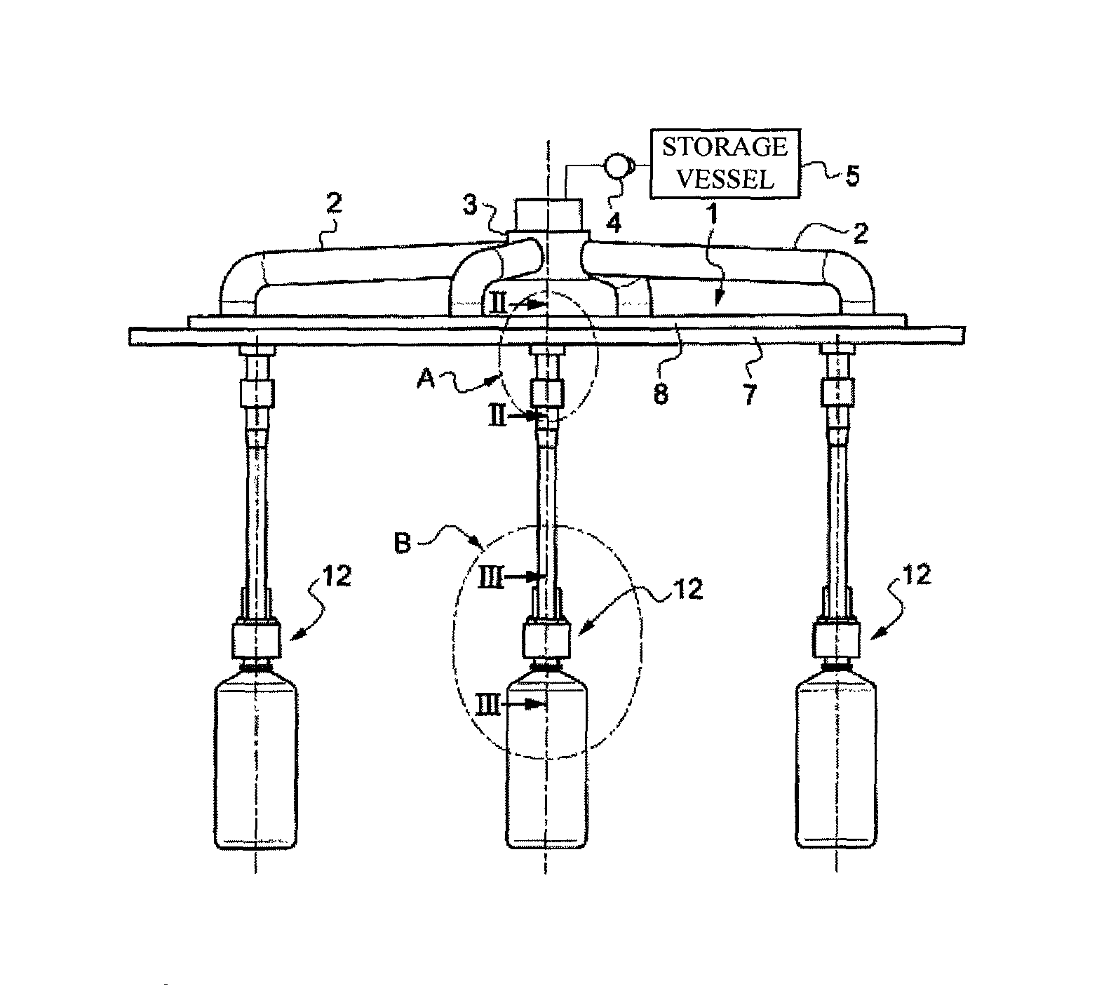
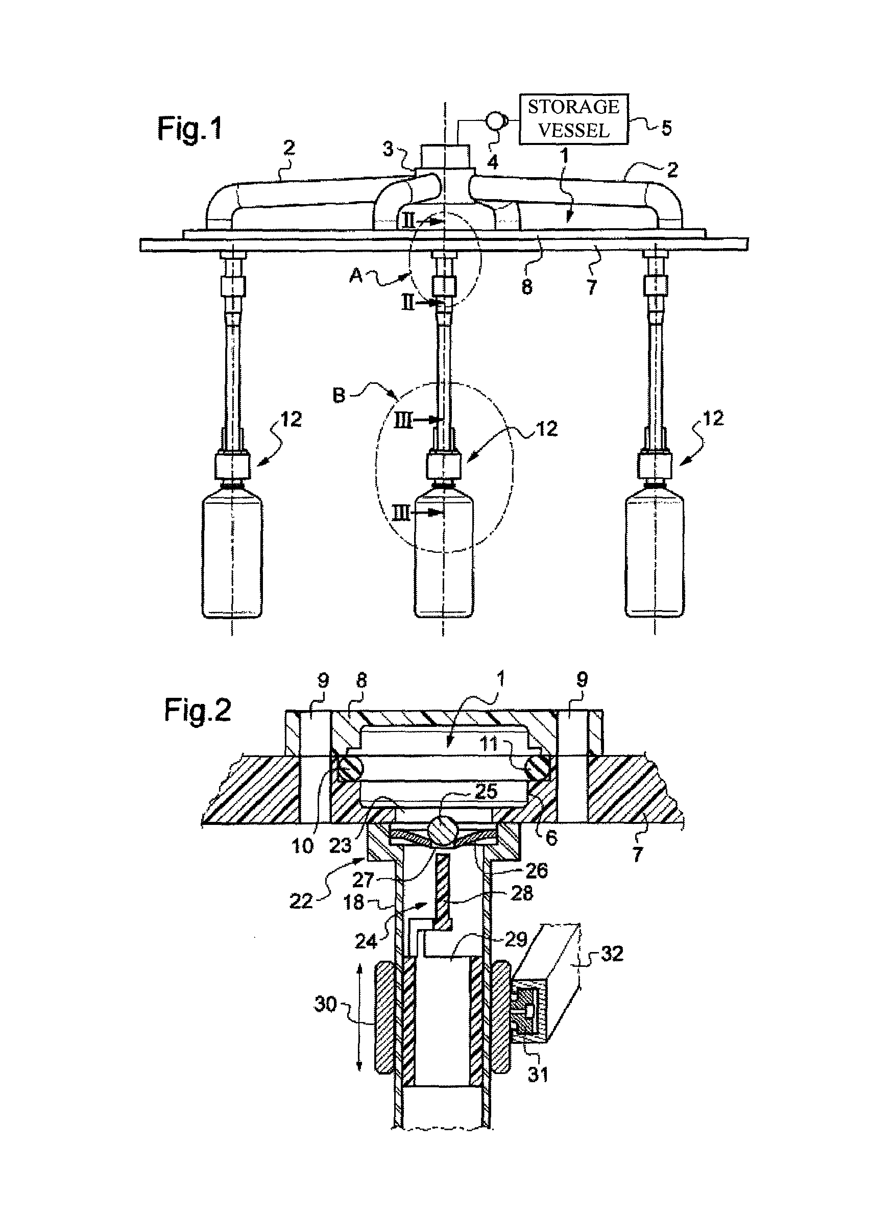
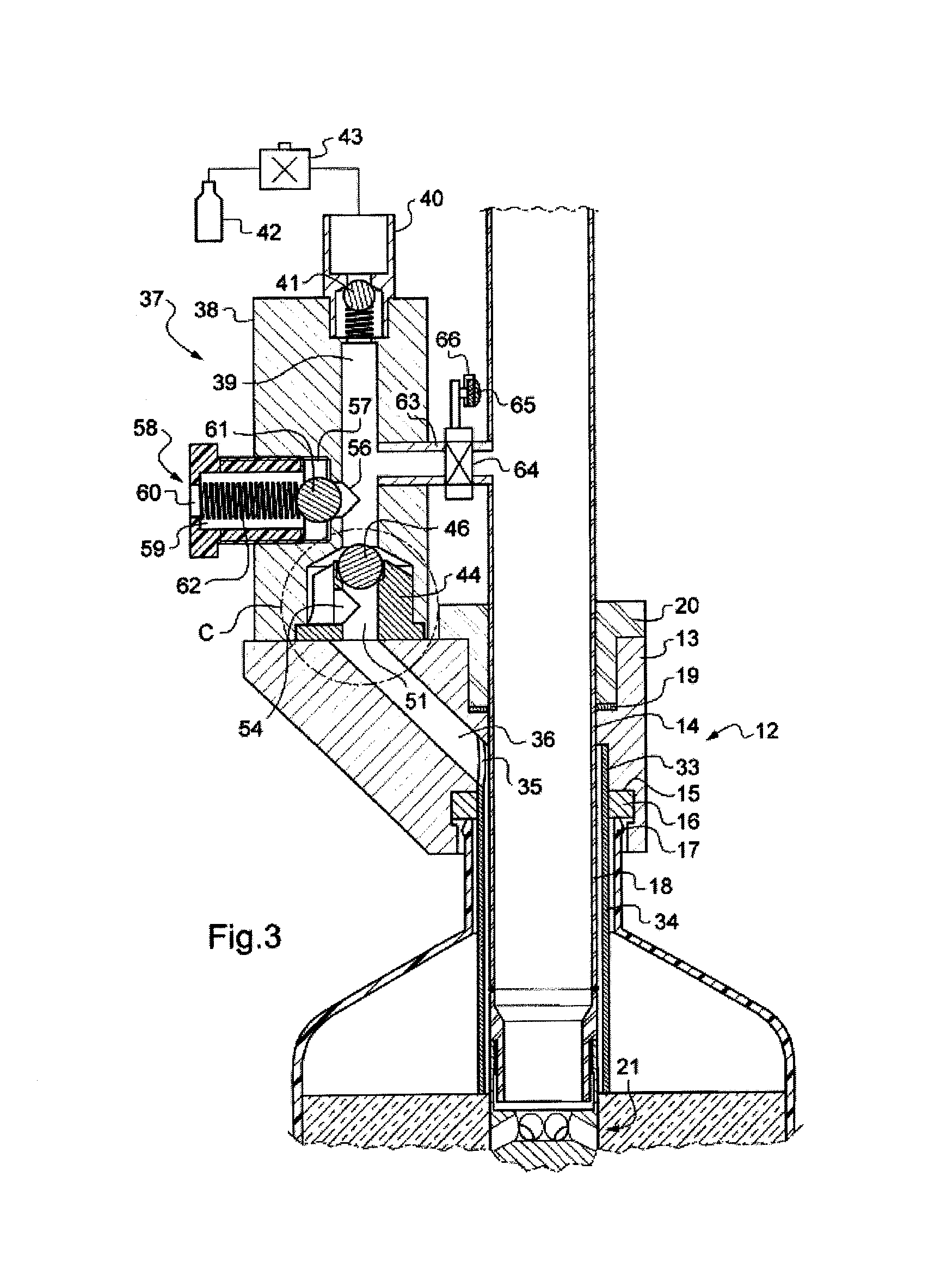
[0036]With reference to FIG. 1, the filling carousel according to the invention comprises an annular supply collector 1 supplied with a liquid under pressure via radial tubes 2 having an extremity connected to the supply collector 1 and an opposite extremity connected to a rotating joint 3 assuring a connection to a source of supply with a liquid under pressure symbolized by a pump 4 associated with a storage vessel 5. As illustrated in FIG. 2, the collector 1 is formed by an annular groove 6 provided in a plate 7, and closed by an annular cover 8 adequately secured to the plate 7 by means of bolts (not illustrated here) extending into drillings 9, the sealing between the plate 7 and the cover 8 being assured by means of o-rings 10 and 11. Filling nozzles 12 are suspended beneath the plate 7. Each filling nozzle 12 comprises a nozzle body 13 traversed by a vertical bore 14 comprising at its lower part a recess 15, inside which there is installed an annular joint 16 forming an annula...


PUM


Abstract

The method for filling containers comprises the following stages: closing an exhaust duct in a calibrated manner (61,62) according to a calibration to an exhaust pressure that is lower than the distribution pressure; placing into position a container to be filled; opening a distribution valve (24) and keeping it open until the closure of an exhaust check valve (46); closing the distribution valve (24).

Description

[0001]The present invention relates to a method for filling containers to a constant level with a still or a sparkling liquid and a filling nozzle for the implementation of this method.BACKGROUND TO THE INVENTION[0002]For the purpose of filling containers to a constant level with a still liquid, filling nozzles are previously disclosed comprising an annular connection part configured to provide a liquid-tight support with a neck of a container and to demarcate a distribution zone; a distribution tube connected to a source of supply of a liquid under a distribution pressure by means of a distribution valve and discharging into the distribution zone; an exhaust duct discharging on the one hand into the distribution zone, and on the other hand via a vent orifice, and an exhaust check valve controlled by a liquid level sensor inside the exhaust duct, interposed in the exhaust duct between the distribution zone and the vent orifice. When filling a container, the air that is present insid...

Claims


Application Information

Patent Timeline
Patent Type & Authority Patents(United States)
IPC IPC(8): B67C3/26
CPCB67C3/262B67C3/2628
Inventor GRAFFIN, JEAN-JACQUES
Owner SERAC GROUP
Why Eureka
Try Eureka