Pneumatic impact tool having two oil inlets

a technology of pneumatic impact and oil inlet, which is applied in the field of pneumatic impact tools, can solve problems such as difficulty in flow, and achieve the effects of quick and uniform flow, effective lubricating effect, and quick and uniform flow

Active Publication Date: 2015-09-22
BASSO IND CORP
View PDF7 Cites 0 Cited by
  • Summary
  • Abstract
  • Description
  • Claims
  • Application Information

AI Technical Summary

Benefits of technology

[0009]The object of this invention is to provide a pneumatic impact tool that can be filled with lubricating oil in a quick and uniform manner.
[0010]According to this invention, a pneumatic impact tool includes a housing, a power output unit, a transmission unit, and an oil seal assembly. The housing has first and second accommodating chambers, and first and second oil inlets in fluid communication with the first and second accommodating chambers, respectively, and permitting lubricating oil to be fed into the first and second accommodating chambers therethrough. The power output unit is centered at a Z-axis, and is disposed in the first accommodating chamber for power outputting. The transmission unit is centered at an X-axis, and is disposed in the second accommodating chamber for transmitting a power to the power output unit. The oil seal assembly prevents flow of the lubricating oil out of the first and second accommodating chambers.
[0011]Since the lubricating oil can be fed into the first and second accommodating chambers through the first and second oil inlets, respectively, it can flow quickly and uniformly into clearances among the above-mentioned components, so as to promote effectively the lubricating effect.

Problems solved by technology

However, the lubricating oil is made of grease, and thus is difficult to flow.

Method used


Image

  • Pneumatic impact tool having two oil inlets
  • Pneumatic impact tool having two oil inlets
  • Pneumatic impact tool having two oil inlets

Examples


Embodiment Construction

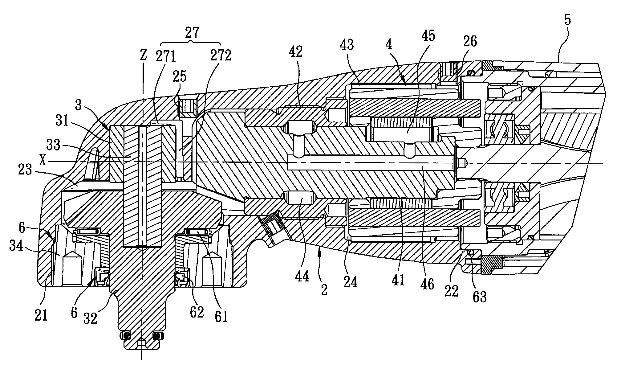
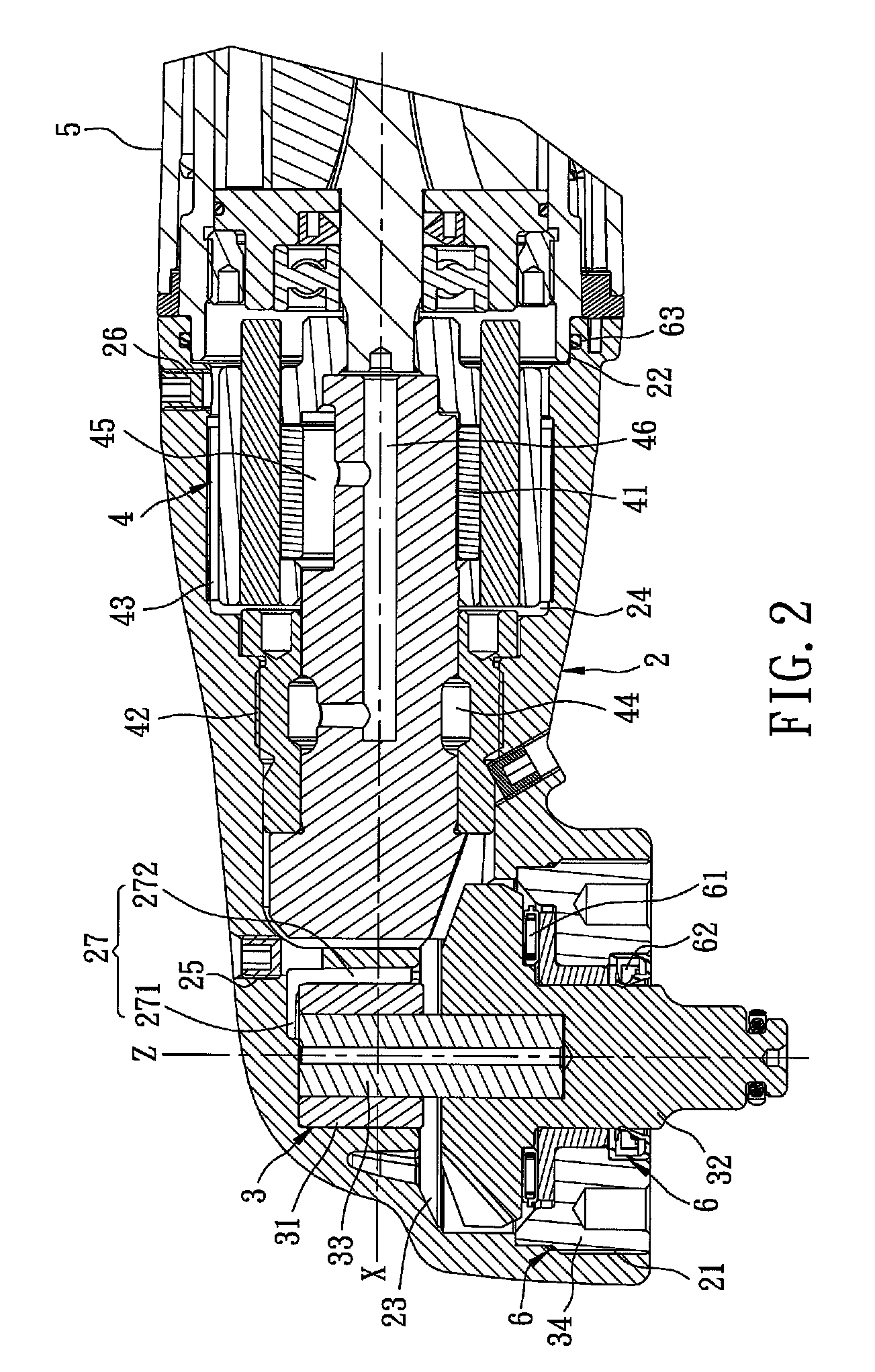
[0015]Referring to FIG. 2, the preferred embodiment of a pneumatic impact tool according to this invention includes a housing 2, a power output unit 3, a transmission unit 4, a shell body 5, and an oil seal assembly.

[0016]The housing 2 has first and second openings 21, 22, first and second accommodating chambers 23, 24 disposed between the first and second openings 21, 22, first and second oil inlets 25, 26 in fluid communication with the first and second accommodating chambers 23, 24, respectively, and an L-shaped oil passage 27 in fluid communication with the first oil inlet 25. The oil passage 27 has a first passage portion 271 parallel to the X-axis, and a second passage portion 272 parallel to the Z-axis. The first oil inlet 25 is disposed between the first and second accommodating chambers 23, 24. The second oil inlet 26 is disposed at a side of the second accommodating chamber 24 distal from the first accommodating chamber 23. In this embodiment, the lubricating oil is an eng...


PUM


Abstract

A pneumatic impact tool includes a housing, a power output unit, a transmission unit, and an oil seal assembly. The housing has first and second accommodating chambers, and first and second oil inlets in fluid communication with the first and second accommodating chambers, respectively, and permitting lubricating oil to be fed into the first and second accommodating chambers therethrough. The power output unit is centered at a Z-axis, and is disposed in the first accommodating chamber for power outputting. The transmission unit is centered at an X-axis, and is disposed in the second accommodating chamber for transmitting a power to the power output unit. The oil seal assembly prevents flow of the lubricating oil out of the first and second accommodating chambers.

Description

CROSS-REFERENCE TO RELATED APPLICATION[0001]This application claims priority of Taiwanese Application No. 101200969, filed on Jan. 16, 2012.BACKGROUND OF THE INVENTION[0002]1. Field of the Invention[0003]This invention relates to a pneumatic tool, and more particularly to a pneumatic impact tool.[0004]2. Description of the Related Art[0005]Referring to FIG. 1, a conventional pneumatic impact tool 1 disclosed in US2011 / 0139474A1 includes a housing 11, a transmission unit 12 extending along an X-axis and disposed rotatably in the housing 11 for power transmission, and a power output unit 13 extending along a Z-axis, disposed rotatably in the housing 11, and geared to the transmission unit 12. The housing 11 has a first accommodating chamber 111 receiving the power output unit 13, a second accommodating chamber 112 receiving the transmission unit 12, and an oil inlet 113 in fluid communication with the second accommodating chamber 112 and permitting lubricating oil to be fed therethrou...

Claims


Application Information

Patent Timeline
Patent Type & Authority Patents(United States)
IPC IPC(8): B23Q11/10B23Q11/12B23Q5/04B25B21/02
CPCB23Q5/045B23Q11/121B25B21/02
Inventor SU, SAN-YIHLAI, CHENG-WEI
Owner BASSO IND CORP
Why Eureka
Try Eureka