Roll stand assembly

a technology of rolling stand and assembly, which is applied in the direction of transportation and packaging, mechanical equipment, web handling, etc., can solve the problems of significant operator injury risk, heavy rolling on extrusion forming equipment, and open relationship may partially or fully clos

Active Publication Date: 2015-09-22
PROCESSING TECH INT
View PDF8 Cites 0 Cited by
  • Summary
  • Abstract
  • Description
  • Claims
  • Application Information

AI Technical Summary

Benefits of technology

[0009]In one form, the invention is directed to a roll stand assembly for processing a sheet product. The roll stand assembly includes a frame and a plurality of rolls on the frame including first and second rolls respectively having first and second axes. The first and second axes are substantially parallel with the first and second rolls operatively positioned on the frame. The first roll has a first sheet engaging surface and a first shaft assembly projecting axially from the first sheet engaging surface. The second roll has a second sheet engaging surface and a second shaft assembly projecting axially from the second sheet engaging surface. The first and second rolls are relatively movable between: a) an operating relationship wherein there is a gap within a first dimensional range between the first and second sheet engaging surfaces with the roll stand assembly in an operative state; and b) an open relationship wherein the gap dimension is outside of the first dimensional range so as to permit access by an operator through the gap to between the first and second rolls. A safety assembly prevents inadvertent changing of the first and second rolls from the open relationship into the operating relationship. The safety assembly includes a first chuck component mounted for movement relative to the frame between: a) a running position wherein the safety assembly is in a disengaged state and the first and second rolls can be relatively repositioned from the open relationship into the operating relationship; and b) a lockout position wherein the safety assembly is in an engaged state and the first chuck component resides between parts of the first and second rolls and prevents relative movement between the first and second rolls in a manner that would allow the first and second rolls to be changed from the open relationship into the operating relationship.
[0015]In one form, the disabling assembly includes a switch assembly that is changeable between on and off states. The switch assembly is changeable from the off state into the on state as an incident of the first chuck component moving from the lockout position into the running position to thereby allow the drive to change the first and second rolls from the open relationship into the operating relationship. The switch assembly is changeable from the on state into the off state as an incident of the first chuck component moving from the running position towards the lockout position to thereby prevent the drive from changing the first and second rolls from the open relationship into the operating relationship.

Problems solved by technology

Rolls on extrusion forming equipment are heavy.
There always exists a possibility that under the weight of the rolls, the gap therebetween that is set with the open relationship may partially or fully close by reason of a failure of the hydraulic drives, a failure of a supporting component, or an inadvertent activation of the drives.
If any of these events occur, there is a significant risk of operator injury.
The industry is devoid of any effective safety assemblies to prevent such occurrences.
It is believed that the lack of such safety assemblies is attributable to the fact that no viable commercial design has been devised that is both effective, easy to operate, and minimally obtrusive in terms of taking up valuable space in and around the working components of the roll stand assembly.

Method used


Image

  • Roll stand assembly
  • Roll stand assembly
  • Roll stand assembly

Examples


Embodiment Construction

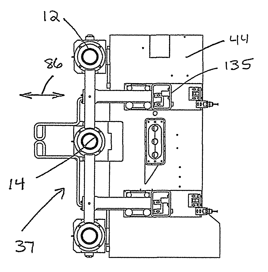
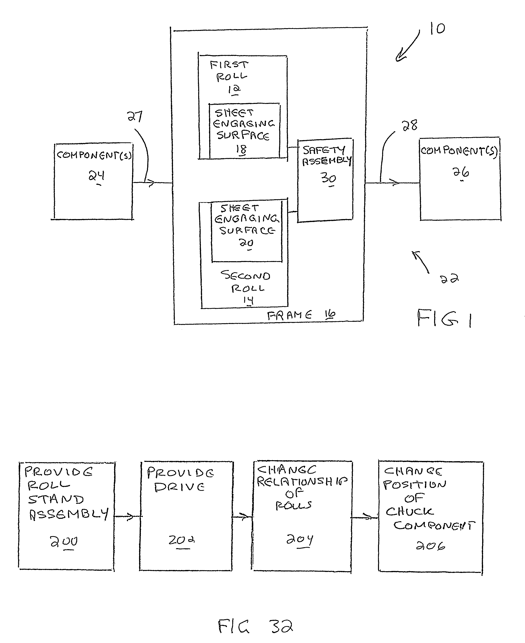
[0064]In FIG. 1, there is a schematic showing of the inventive roll stand assembly at 10. The roll stand assembly 10 has at least first and second cooperating rolls 12, 14, respectively. The rolls 12, 14 are mounted upon a frame 16 for rotation about substantially parallel axes. The rolls 12, 14 have sheet engaging surfaces 18, 20 that cooperate during the sheet formation / handling process.

[0065]The roll stand assembly 10 may be a stand-alone unit or may be part of a system, shown at 22, with one or more upstream components 24 and one or more downstream components 26. The upstream components 24 may direct a moldable material or a sheet product 27 to the roll stand assembly 10 with a sheet product 28 directed from the roll stand assembly 10 to the downstream component(s) 26.

[0066]The schematic showing of the roll stand assembly 10 and overall system 22 is made to encompass any roll stand assembly construction, used alone or as part of any system, in which there are cooperating rolls b...


PUM

PropertyMeasurementUnit
angleaaaaaaaaaa
gap dimensionaaaaaaaaaa
lengthaaaaaaaaaa

Abstract

A roll stand assembly for processing a sheet product with a plurality of rolls on a frame. A first roll has a first sheet engaging surface and a first shaft assembly. A second roll has a second sheet engaging surface and a second shaft assembly. The first and second rolls are relatively movable between: a) an operating relationship; and b) an open relationship. A safety assembly prevents inadvertent changing of the first and second rolls from the open relationship into the operating relationship. The safety assembly includes a first chuck component mounted for movement relative to the frame between: a) a running position wherein the safety assembly is in a disengaged state; and b) a lockout position.

Description

BACKGROUND OF THE INVENTION[0001]1. Field of the Invention[0002]This invention relates to roll stand assemblies as used to form and handle sheet materials and, more particularly, to a roll stand assembly incorporating a safety assembly to maintain a gap between adjacent rolls.[0003]2. Background Art[0004]A multitude of roll stand assemblies currently exists to facilitate sheet formation, processing, and handling. During extrusion sheet formation, a flowable mold material is introduced at a nip location between adjacent rolls which, in addition to forming a sheet configuration, effect advancement thereof to a downstream location for further processing, joinder with other components, etc., preparatory to eventual accumulation of a final product at a point of use. There are virtually an endless number of processing, formation, and handling structures devised for such sheets. Typical of all such roll stand assemblies is the utilization of cooperating rolls that are mounted on a frame fo...

Claims


Application Information

Patent Timeline
Patent Type & Authority Patents(United States)
IPC IPC(8): B65H20/02B65H16/02F16P1/00B65H26/00B29C47/00B65H16/00B29C48/08
CPCB65H16/021B65H20/02B65H26/00F16P1/005B29C47/004B29C47/0021B65H16/00B65H2407/11D21G5/005B29C48/08B29C48/0011B65H2407/10
Inventor HANSON, DANA R.GRITZNER, MITCHELL L.
Owner PROCESSING TECH INT
Why Eureka
Try Eureka