Engine system having a backflow valve and method for operation thereof

a technology of backflow valve and engine, which is applied in the direction of machines/engines, pressure lubrication, lubrication elements, etc., can solve the problems of increasing the amount of blow-by gasses emitted, increasing the oil consumption of the engine, and increasing vehicle emissions, so as to reduce vehicle emissions, reduce the amount of blow-by gasses, and increase vehicle emissions

Active Publication Date: 2015-09-22
FORD GLOBAL TECH LLC
View PDF11 Cites 12 Cited by
  • Summary
  • Abstract
  • Description
  • Claims
  • Application Information

AI Technical Summary

Benefits of technology

[0002]In some engines, oil and combustion gases may flow past cylinder in the engine into an unsealed crankcase, thereby increasing vehicle emissions. Therefore, positive crankcase ventilation (PCV) systems have been developed to decrease vehicle emissions. The crankcase ventilation systems may include a sealed crankcase which vents crankcase gas into an intake conduit. At the same time, fresh air may be flowed into the sealed crankcase. In this way, air may be circulated through the crankcase and blow-by gases may be flowed to the intake system to reduce the amount of blow-by gasses emitted from the vehicle.
[0003]U.S. Pat. No. 8,347,865 discloses a PCV system including an oil separator in fluidic communication with an oil drain passage flowing oil separated from the blow-by gasses to an oil pan. However, the inventors have recognized several drawbacks with the PCV system disclosed in U.S. Pat. No. 8,347,865. The outlet of the oil drain passage may not be submerged in oil during some operating conditions. For instance, during cornering or other vehicle maneuvers the oil may be moved away from the outlet of the oil drain. Consequently, the oil drain passage may experience elevated pressures and oil may travel up the drain passage and past the oil separator into the intake system, increasing oil consumption in the engine and decreasing combustion efficiency.
[0005]In this way, a technical result of stopping or inhibiting oil backflow in the oil drain passage may accomplished during certain operating conditions and oil flow may be metered during other operating conditions. In one example, the first and second configurations may be implemented based on pressure in the sealed crankcase. An oil level stick may extend down the oil drain passage. In this way, the amount of oil may be ascertained by the vehicle operation when the backflow valve is in the first configuration. The first configuration may be initiated when a pressure in the crankcase is below a threshold value and the second configuration may be initiated when the pressure is above the threshold value. In this way, oil may flow into the oil drain passage during some conditions, enabling the oil level stick to be used as an oil level indicator and during other conditions oil backflow through the passage may be inhibited to reduce the likelihood of oil traveling through the drain passage into the intake system. As a result, combustion efficiency may be increased. The technical results achieved by the engine system include enabling an oil drain passage to be used for oil level indication as well as for a drain for separated oil and increasing the engine's combustion efficiency by reducing the likelihood of intake air contamination.

Problems solved by technology

In some engines, oil and combustion gases may flow past cylinder in the engine into an unsealed crankcase, thereby increasing vehicle emissions.
However, the inventors have recognized several drawbacks with the PCV system disclosed in U.S. Pat. No. 8,347,865.
Consequently, the oil drain passage may experience elevated pressures and oil may travel up the drain passage and past the oil separator into the intake system, increasing oil consumption in the engine and decreasing combustion efficiency.

Method used


Image

  • Engine system having a backflow valve and method for operation thereof
  • Engine system having a backflow valve and method for operation thereof
  • Engine system having a backflow valve and method for operation thereof

Examples


Embodiment Construction

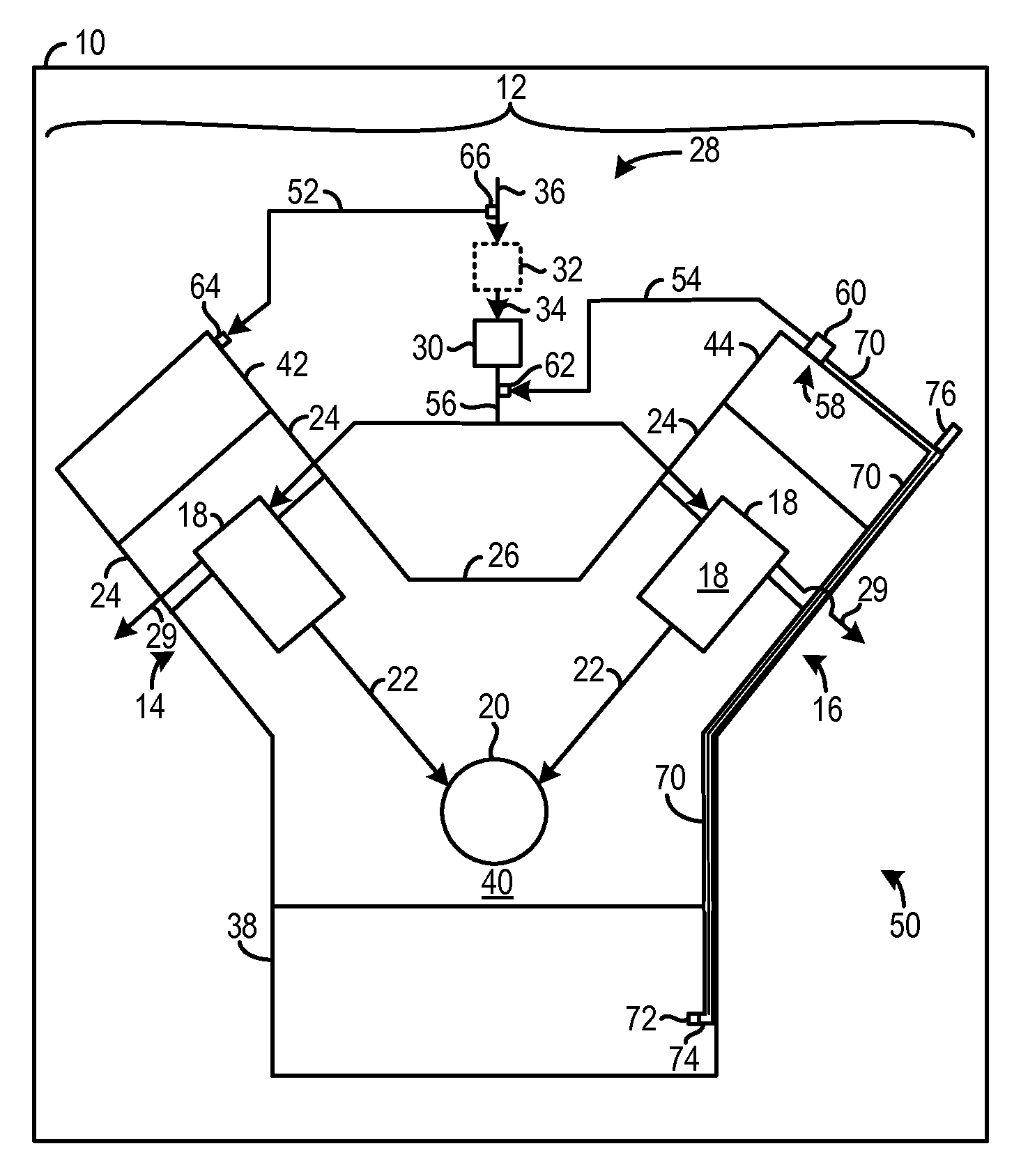
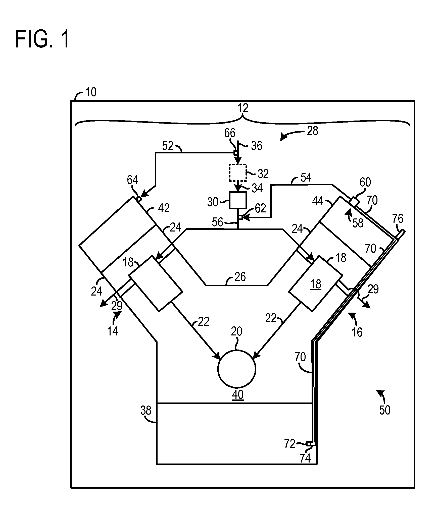
[0013]A positive crankcase ventilation (PCV) system is described herein. The PCV system includes a backflow valve coupled to an outlet of an oil drain passage in a sealed crankcase. The backflow valve is operable in two configurations. The first configuration enables oil backflow into the oil drain passage and the second configuration inhibits oil from entering the oil drain passage. The configurations may be initiated based on the pressure in the sealed crankcase. Specifically, the second configuration may be initiated when the crankcase pressure is above a threshold value and the first configuration may be initiated when the crankcase pressure is below a threshold value. It will be appreciated that in some examples, the aforementioned threshold values may be equivalent. In this way, oil may flow into the oil drain passage during certain conditions, enabling an oil level stick extending through the oil drain passage to be used as an oil level indicator. However, during other condit...


PUM


Abstract

An engine system is described. The engine system includes an oil drain passage in fluidic communication with an oil separator. The engine system further includes a backflow valve positioned at an outlet of the oil drain line, the backflow valve having a first configuration where the valve provides a predetermined amount of oil backflow into the oil drain passage and a second configuration where the valve inhibits oil backflow into the oil drain passage.

Description

FIELD[0001]The present disclosure relates a positive crankcase ventilation system and method for operation thereof.BACKGROUND AND SUMMARY[0002]In some engines, oil and combustion gases may flow past cylinder in the engine into an unsealed crankcase, thereby increasing vehicle emissions. Therefore, positive crankcase ventilation (PCV) systems have been developed to decrease vehicle emissions. The crankcase ventilation systems may include a sealed crankcase which vents crankcase gas into an intake conduit. At the same time, fresh air may be flowed into the sealed crankcase. In this way, air may be circulated through the crankcase and blow-by gases may be flowed to the intake system to reduce the amount of blow-by gasses emitted from the vehicle.[0003]U.S. Pat. No. 8,347,865 discloses a PCV system including an oil separator in fluidic communication with an oil drain passage flowing oil separated from the blow-by gasses to an oil pan. However, the inventors have recognized several drawb...

Claims


Application Information

Patent Timeline
Patent Type & Authority Patents(United States)
IPC IPC(8): F01M1/04F01M11/02F01M13/02F02B75/02F01M1/16
CPCF01M11/02F01M13/028F01M1/04F01M1/16F02B2075/025F02B2075/027F01M13/04F01M2013/0494
Inventor VALENCIA, FRANK ACIERNO
Owner FORD GLOBAL TECH LLC
Why Eureka
Try Eureka