Co-axial adjustable damping assembly

a damping assembly and coaxial adjustment technology, applied in the direction of shock absorbers, springs/dampers design characteristics, vibration dampers, etc., can solve the problems of insufficient speed, insufficient rotation of cone rods, and slow movement of pistons, so as to quickly activate or lock the damping assembly, the effect of quick response and sensitive response of the damping assembly

Inactive Publication Date: 2015-10-06
RACINGBROS INT
View PDF6 Cites 7 Cited by
  • Summary
  • Abstract
  • Description
  • Claims
  • Application Information

AI Technical Summary

Benefits of technology

[0010]The primary object of the present invention is to provide a co-axial adjustable damping assembly which has a switching device and the switching device is operated by operation to the lever to quickly activate or lock the damping assembly.
[0011]Another object of the present invention is to provide a co-axial adjustable damping assembly wherein the cylinder unit is co-axially connected to the switching device, and cooperated with the cam part so that when the knob is rotated one revolution, all of the adjustments stages are completed. The travel of the piston rod is short and the damping assembly is reacted quickly and sensitively.
[0013]A further object of the present invention is to provide a co-axial adjustable damping assembly which allows the user to switch or adjust the damping assembly at the same position without moving the hand.

Problems solved by technology

On the contrary, when a smaller amount of the hydraulic oil or air can pass within a certain period of time, this means that the piston moves slower and larger damping force is generated.
However, both of the two prior arts cannot quickly lock the path, it takes time, at least three seconds, to rotate the cone-shaped rod and which is not quick enough.

Method used


Image

  • Co-axial adjustable damping assembly
  • Co-axial adjustable damping assembly
  • Co-axial adjustable damping assembly

Examples


Embodiment Construction

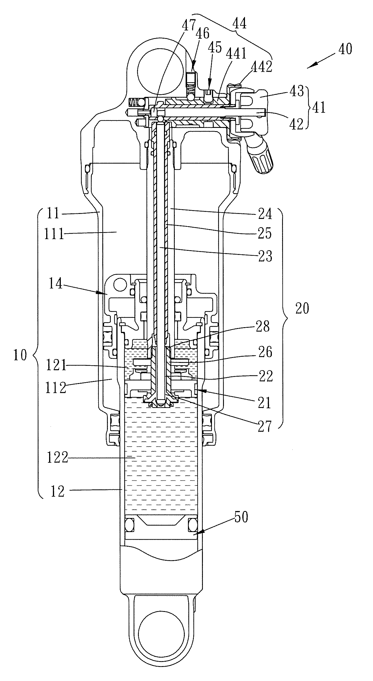
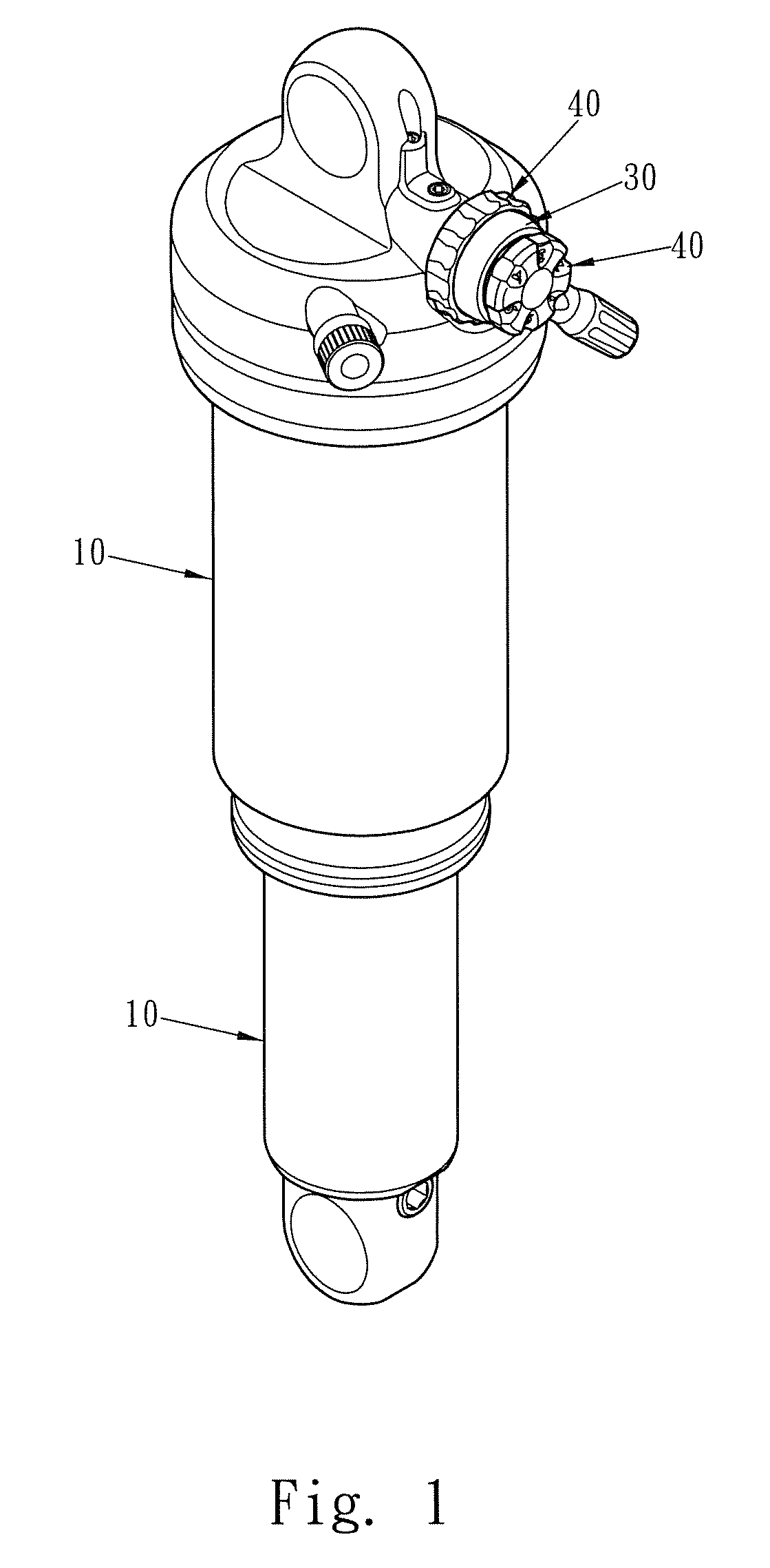
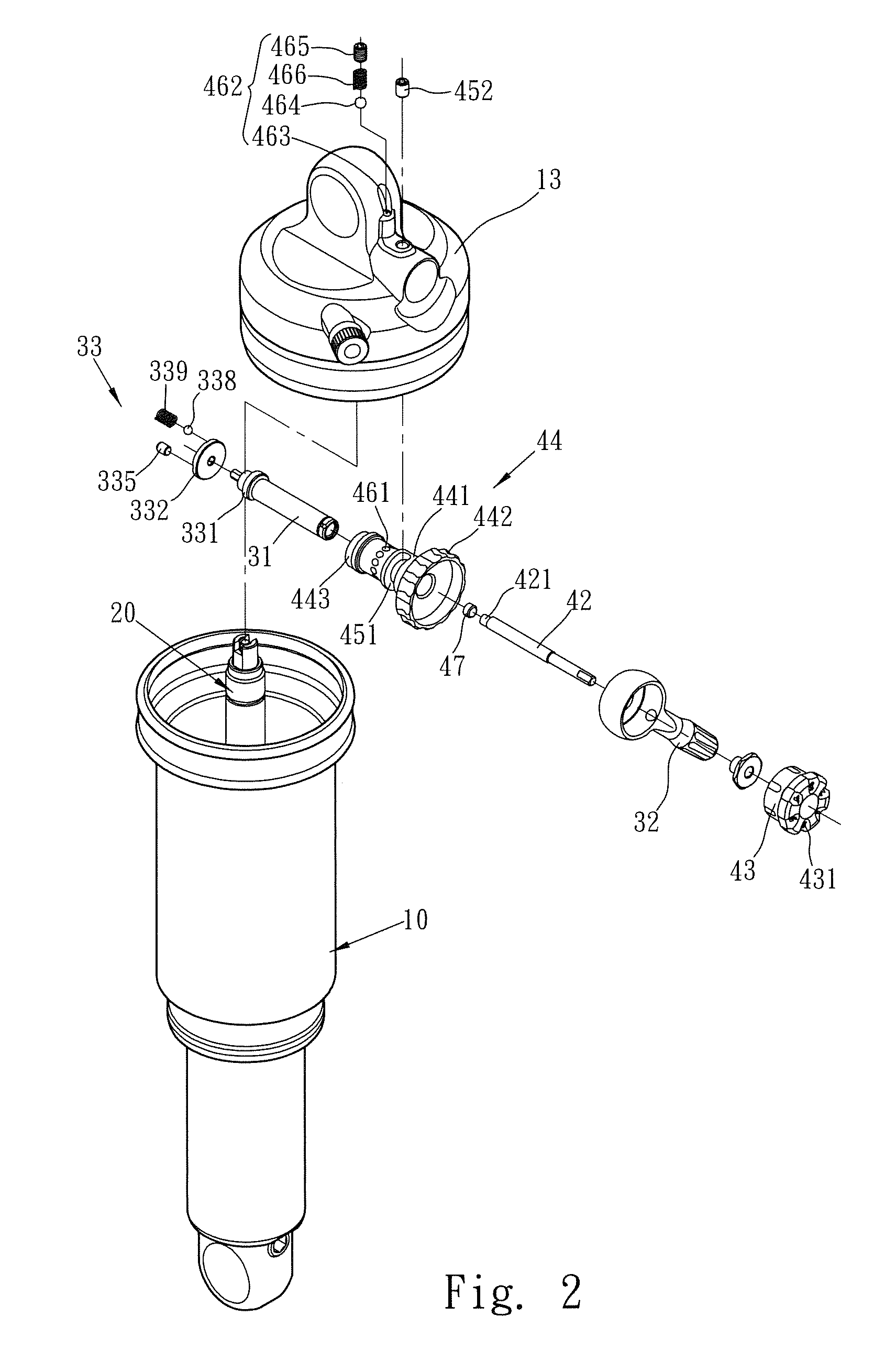
[0037]Referring to FIGS. 1 to 6, the co-axial adjustable damping assembly of the present invention comprises a cylinder unit 10, a valve unit 20 in the cylinder unit 10, a switching device 30, a damping device 40 and a pressure stabilization unit 50.

[0038]The cylinder unit 10 comprises an outer case 11 and an inner case 12 which is linearly and movably inserted into the outer case 11. The outer case 11 has a cap 13 to seal one end of the outer case 11. A piston unit 14 is connected to one end of the inner case 12 and movably in contact with inside of the outer case 11. The piston unit 14 and the inner case 12 are co-movable linearly. The piston unit 14 defines the interior of the outer case 11 into a first air chamber 111 and a second air chamber 112.

[0039]The valve unit 20 is located in the center of the outer case 11 and the first end of the valve unit 20 extends through the piston unit 14 and is inserted into the inner case 12. A piston 21 is connected to the first end of the val...


PUM


Abstract

A co-axial adjustable damping assembly includes a cylinder unit having an outer case with a cap, and an inner case having a piston unit which movably contacts inside of the outer case. A valve unit extends through the piston unit and is inserted into the inner case. A piston is connected to the valve unit and defines a first oil chamber and a second oil chamber in the inner case. A path communicates between the first and second oil chambers. A piston rod extends through the inner case, the outer case, the piston unit and the piston. A switching device is connected to the cap and has a first tube which has a cam part contacting the piston rod. A damping device has a driving rod inserted into the first tube. The driving rod is rotated to move the piston rod linearly to adjust the path.

Description

FIELD OF THE INVENTION[0001]The present invention relates to a damping assembly, and more particularly, to damping assembly using air or hydraulic oil and the damping value can be adjusted by changing the volume of the hydraulic oil.BACKGROUND OF THE INVENTION[0002]The conventional damping assembly is generally used in vehicles or machines and provides velocity-reduction and buffering features. The conventional damping assemblies are generally cataloged by mechanical damping assembly, hydraulic damping assembly and hybrid damping assembly which uses both air and hydraulic oil. The mechanical damping assembly absorbs shocks and vibration by operation to the mechanism to provide the velocity-reduction and buffering features. The hydraulic damping assembly uses hydraulic related parts and hydraulic oil is filled in the assembly so as to absorb the shocks and vibrations. The hybrid damping assembly uses both hydraulic oil and air related parts, hydraulic oil and air are filled in the as...

Claims


Application Information

Patent Timeline
Patent Type & Authority Patents(United States)
IPC IPC(8): F16F9/56F16F9/46
CPCF16F9/56F16F9/462F16F2230/0064
Inventor CHEN, MENG-TSUNG
Owner RACINGBROS INT
Why Eureka
Try Eureka