
Withdrawable unit for an electric switching device

a technology of electric switching device and withdrawable unit, which is applied in the direction of switchgear, switchgear with withdrawable carriage, air-break switch, etc., can solve the problems of hidden risk of locking being forgotten, the opening of the withdrawable unit in the wall, and the withdrawalable unit not passing superior types of protection

Active Publication Date: 2015-10-06
EATON INTELLIGENT POWER LIMITED
View PDF14 Cites 16 Cited by
  • Summary
  • Abstract
  • Description
  • Claims
  • Application Information

AI Technical Summary

Benefits of technology

The access door in this patent is connected to seals at the edge of the door or the frame, which helps to create a tight seal and prevent water and dust from getting inside. This results in a more reliable and effective access point for the control side of the housing. Overall, this design allows for a withdrawable unit that passes industry-specific tests for protection against dust and water.

Problems solved by technology

Analogous locking for a withdrawable unit equipped with a device for inserting the power circuit breaker does not, however, have to be undertaken by hand, which would then have the hidden risk of locking being forgotten.
The necessity of access to the control elements cause openings in the walls of the withdrawable unit.
Therefore such withdrawable units do not pass superior types of protection, like protection against dust or water.

Method used


Image

  • Withdrawable unit for an electric switching device
  • Withdrawable unit for an electric switching device
  • Withdrawable unit for an electric switching device

Examples


Embodiment Construction

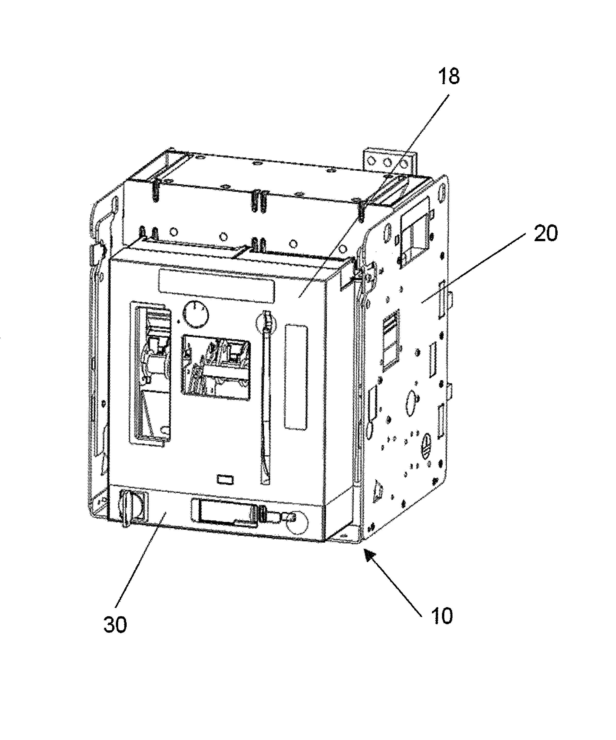
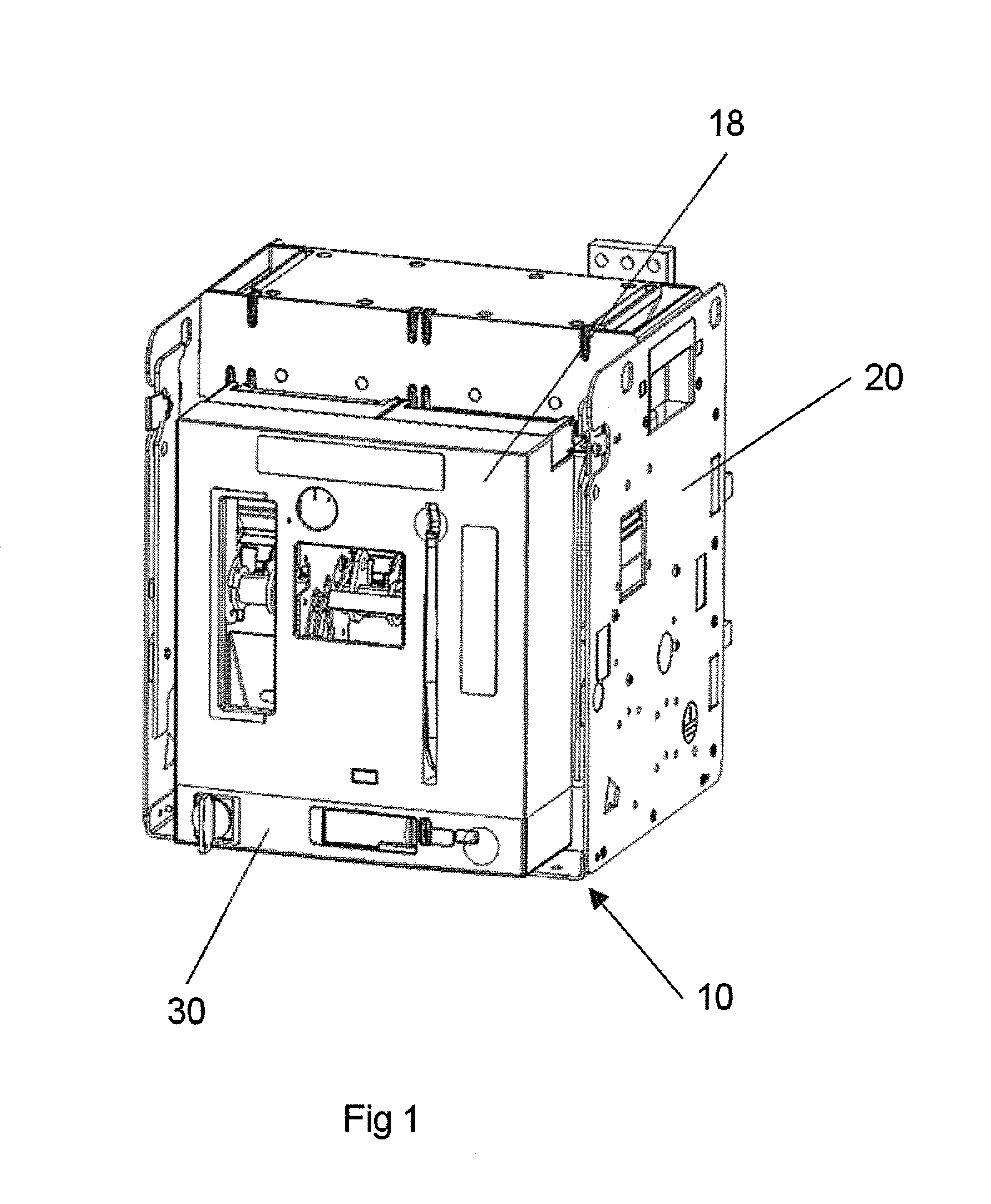
[0027]An embodiment of the current invention provides a withdrawable unit system for an electric switching devise, which is able to pass tests due to superior types of protection against dust and water, like IP 40 pursuant DIN EN 60529, whilst it is able to move an electric switching device like a power circuit breaker from a operating position to an withdrawn position via a test position, where the unit is automatically secured in all three positions, and the unit can be unlocked from these secured positions in a safe and easy way, and vice-versa.

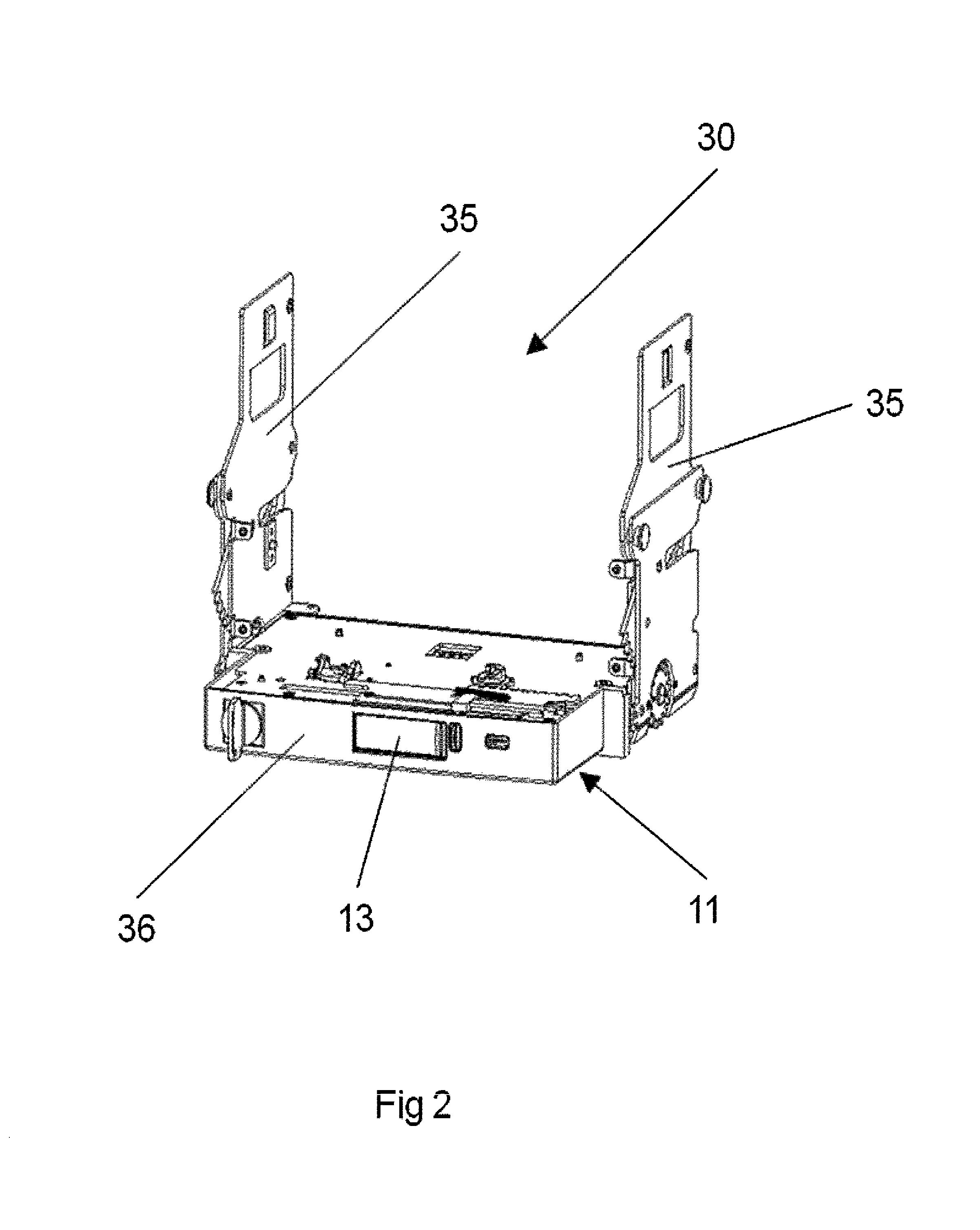
[0028]According to a first aspect, the present invention suggests a withdrawable unit system, which comprises at least a rack and a moveable unit having a housing which contains at least means for moving the electric switching device relatively to the rack, a slide, a locking device, and the housing having a control side with an access door, which is able to be opened and closed, and which gives access to all control elements of the withdr...


PUM


Abstract

A withdrawable unit system for an electric switching device, having a housing containing a access door, which gives access to all control elements of the unit and can be closed as tightly as required by international standards, such as DIN EN 60529. The withdrawable unit system optionally has a moveable unit capable of blocking and releasing the electrical switching device in and from at least three defined positions withdrawn, test and plugged-in by using a slide, a lever, and notches with dedicated notch blocking devices.

Description

CROSS-REFERENCE TO RELATED APPLICATIONS[0001]This application is a U.S. national phase application under 35 U.S.C. §371 of International Application No. of PCT / EP2011 / 073637 filed on Dec. 21, 2011, and claims benefit to European Patent Application No. 10196281.9, filed on Dec. 21, 2010. The international application was published in English on Jun. 28, 2012, as WO 2012 / 085116 A1 under PCT Article 21(2).FIELD[0002]The invention relates to a withdrawable unit system for an electric switching device. Such withdrawable unit systems are accessories for electric switching devices, especially power circuit breakers, which enable the user to withdraw the switching device out of a switchgear for maintenance, replacement or for demonstration of a viewable isolating distance. An additional advantage in using such withdrawable unit systems lies in the fact that the energy feed side of the switchgear must not be disconnected in such cases, i.e. live removal of the electric switching device is po...

Claims


Application Information

Patent Timeline
IPC IPC(8): H02B11/02H02B11/133
CPCH02B11/02H02B11/133
Inventor FLEITMANN, GREGORKUTSCHE, WOLFGANG
Owner EATON INTELLIGENT POWER LIMITED
Learn More