Rotary type vibration wave driving apparatus

a driving apparatus and rotary technology, applied in electrical equipment, generators/motors, electric motors, etc., can solve the problems of reducing the efficiency and generation of squealing sounds, reducing the durability and reducing the output torque of the vibration wave motor. , to achieve the effect of reducing local wear of the contact member and reducing the deterioration of performan

Inactive Publication Date: 2015-10-06
CANON KK
View PDF24 Cites 2 Cited by
  • Summary
  • Abstract
  • Description
  • Claims
  • Application Information

AI Technical Summary

Benefits of technology

[0022]In view of the above described problem, it is an object of the present invention to provide a rotary type vibration wave driving apparatus which is capable of reducing local wear of a contacting member and of reducing deterioration of performance due to long term operation.
[0024]According to the present invention, it is possible to realize a rotary type vibration wave driving apparatus which is capable of reducing local wear of the contacting member and of reducing deterioration of the performance due to long time operation.

Problems solved by technology

This causes reduction of efficiency and generation of squealing sounds, and also causes wear.
Thus, when the applied pressure force is reduced, the output torque of the vibration wave motor is also restricted.
As described above, in the configuration of the contacting portion of the conventional vibration wave motor, there is a problem that the durability of the vibration wave motor is deteriorated by the local wear of the contacting portion.

Method used


Image

  • Rotary type vibration wave driving apparatus
  • Rotary type vibration wave driving apparatus
  • Rotary type vibration wave driving apparatus

Examples


first embodiment

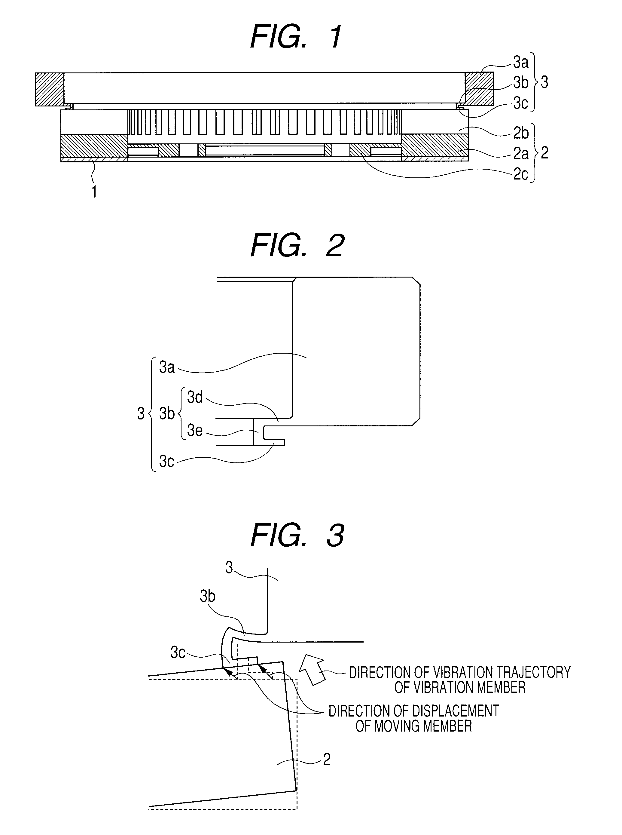
[0045]A rotary type vibration wave driving apparatus according to a present embodiment illustrated in FIG. 1 is formed in an annular shape, and includes a piezoelectric element 1, an vibration member 2, and a moving member 3.

[0046]The piezoelectric element 1 is a electro-mechanical energy conversion element which converts an electrical amount into a mechanical amount, and is coupled to the vibration member 2.

[0047]The vibration member 2 is a metallic elastic member, and is configured by a base 2a, protrusions 2b, and a flange portion 2c that is extended from the base 2a and is used to fix the vibration member 2.

[0048]The protrusions 2b are arranged concentrically around the central axis of the vibration member 2 along the outer diameter side of the base 2a. The surface of the protrusions 2b on the side of the moving member 3 is the surface which is brought into contact with the moving member 3.

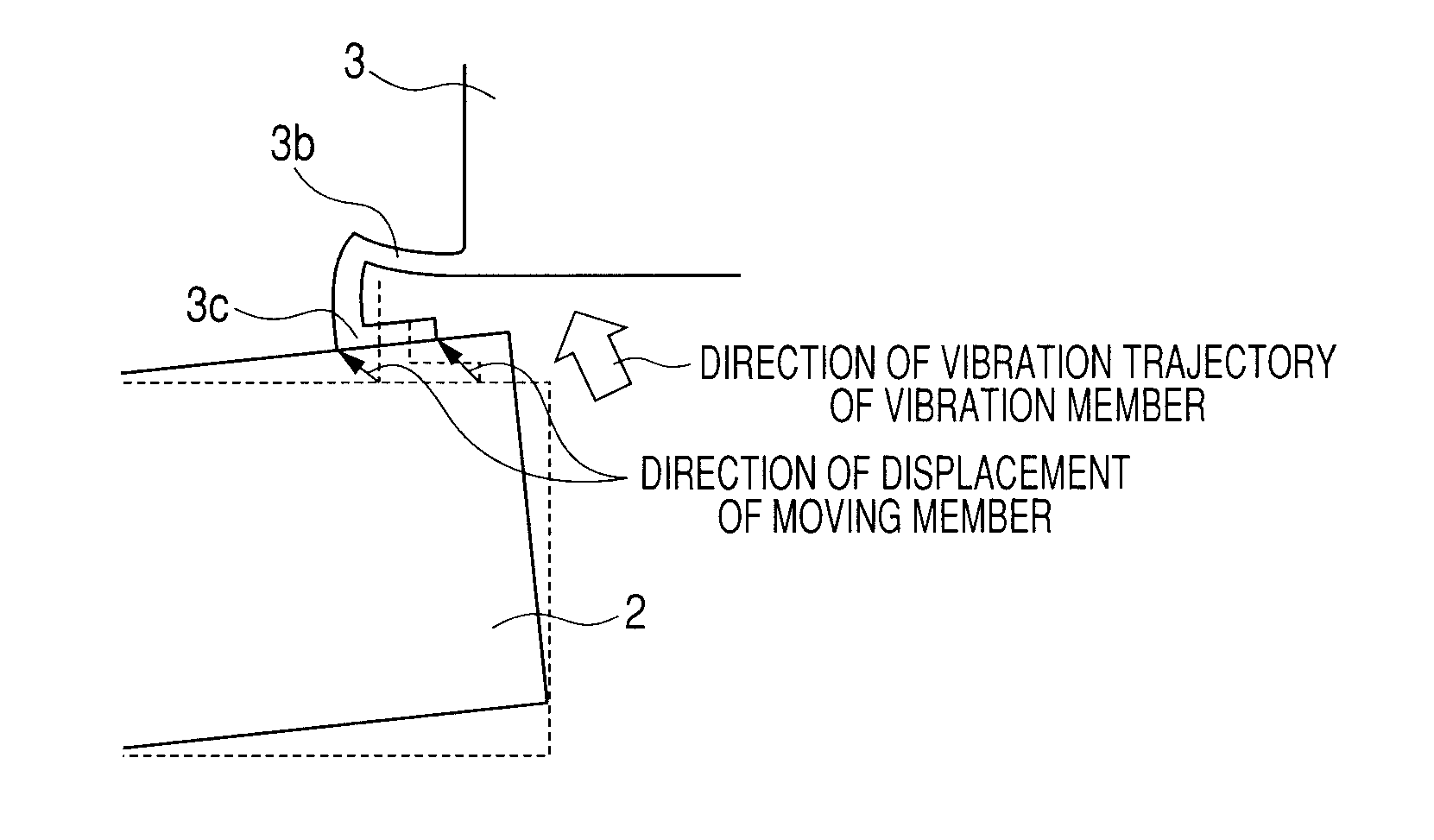
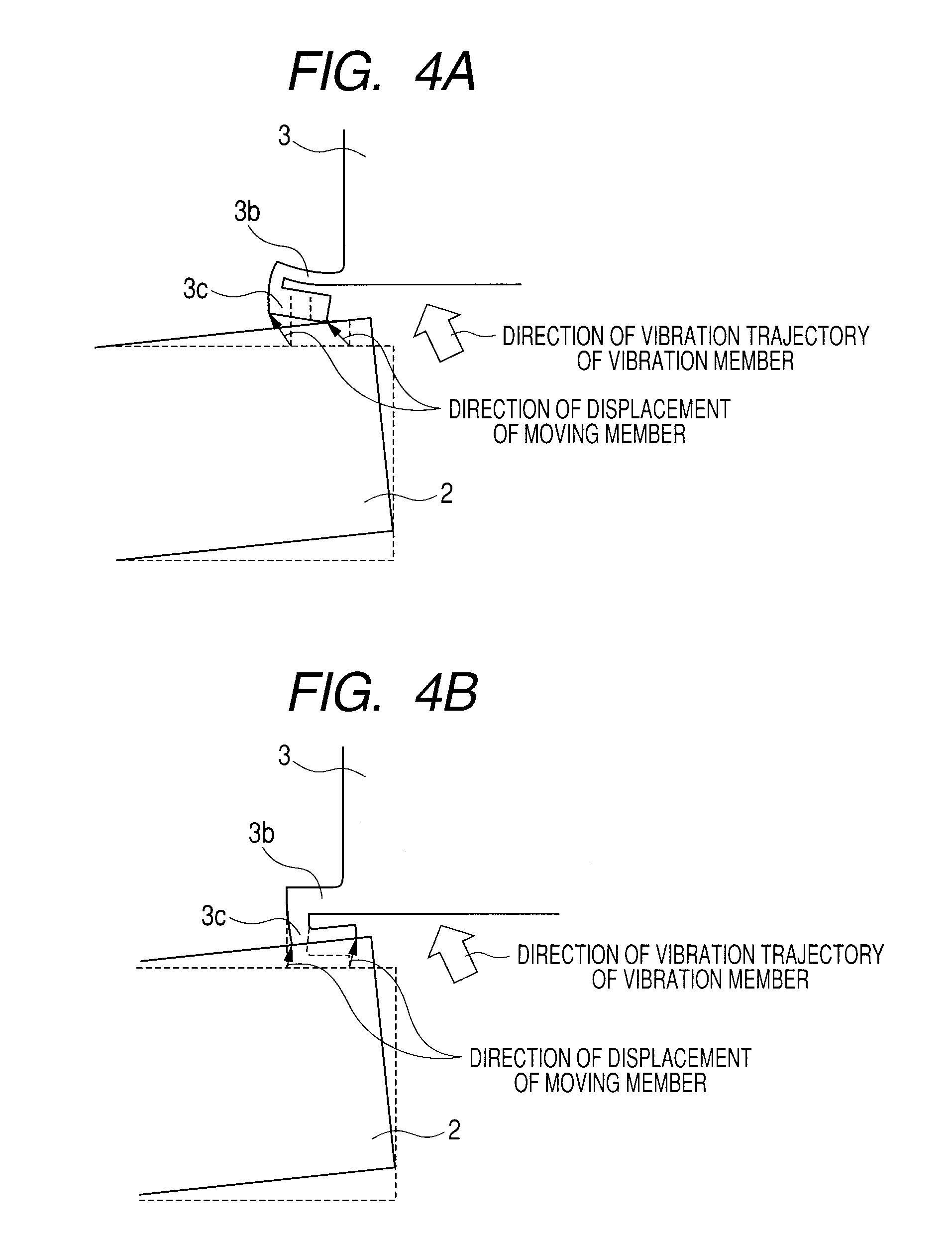
[0049]The moving member 3 is configured by an annular main body portion 3a formed by an el...

second embodiment

[0083]A second embodiment according to the present invention is different from the above described first embodiment in that the supporting portion, the contacting portion, and the main body portion are configured as illustrated in FIG. 6A.

[0084]The other elements (piezoelectric element 1 and vibration member 2) of the present embodiment are the same as those corresponding to the above described first embodiment, and hence the description thereof is omitted.

[0085]Note that the configuration illustrated in FIG. 6A according to the present embodiment corresponds to FIG. 2, and FIG. 5A, FIG. 5B, FIG. 5C and FIG. 5D.

[0086]In FIG. 6A, a supporting portion 53b and a contacting portion 53c are integrally formed by sheet metal press working.

[0087]The supporting portion 53b and the contacting portion 53c are made of a stainless steel plate, and are subjected to quenching and tempering treatment to improve the durability.

[0088]A main body portion 53a is formed in an annular shape, and the main...

third embodiment

[0100]A third embodiment according to the present invention is different from the above described first embodiment in that the supporting portion, the contacting portion, and the main body portion are configured as illustrated in FIG. 7A.

[0101]The other elements (piezoelectric element 1 and vibration member 2) of the present embodiment are the same as those corresponding to the above described first embodiment, and hence the description thereof is omitted.

[0102]Note that the configuration of the present embodiment illustrated in FIG. 7A corresponds to FIG. 2, FIG. 5A, FIG. 5B, FIG. 5C, FIG. 5D, FIG. 6A, and FIG. 6B.

[0103]In FIG. 7A, a contacting portion 73c is extended to the outer diameter section side from a second supporting portion 73e, and the inner diameter side end portion of the contacting portion 73c is made to project to the inner diameter side from the second supporting portion 73e.

[0104]The projecting length of the contacting portion 73c to the inner diameter side is su...


PUM


Abstract

A rotary type vibration wave driving apparatus which is capable of reducing local wear of a contacting member and of reducing performance deterioration due to long term operation is provided. The apparatus includes a electro-mechanical energy conversion element, an vibration member fixed to the electro-mechanical energy conversion element and vibrated by a voltage being supplied to the electro-mechanical energy conversion element, and a moving member being brought into contact with the vibration member and frictionally driven by the vibration, and is configured such that the moving member includes a supporting portion extended from the main body portion of the moving member, and a contacting portion extended from the supporting portion and being brought into contact with the vibration member, and such that each of the supporting portion and the contacting portion is configured to be elastically deformable in the rotation axis direction of the moving member.

Description

TECHNICAL FIELD[0001]The present invention relates to a rotary type vibration wave driving apparatus.BACKGROUND ART[0002]Generally, a vibration driven apparatus applied to a vibration wave motor has an vibration member in which vibration waves are formed, and a moving member which is brought into pressure contact with the vibration member, and obtains driving force by making the vibration member and the moving member frictionally driven by the vibration waves.[0003]Therefore, a contacting portion arranged between the vibration member and the moving member extracts the driving force by repeating contact and separation with and from the vibration member while being deformed so as to follow the vibration of the vibration member.[0004]A prior art form of a vibration wave motor of this kind is illustrated in FIG. 9A. (see Japanese Patent Application Laid-Open No. S61-224882). In FIG. 9A, a vibration member 122 is formed into an annular shape, and a plurality of protrusions 122b are forme...

Claims


Application Information

Patent Timeline
Patent Type & Authority Patents(United States)
IPC IPC(8): H02N2/12H02N2/16H02N2/10H02N2/02
CPCH02N2/163H02N2/103H02N2/026H02N2/0065
Inventor SUEFUJI, KEIKIMURA, ATSUSHIMORI, TAKAO
Owner CANON KK
Why Eureka
Try Eureka