Power over ethernet lighting system

a technology of power over ethernet and lighting system, applied in the direction of lighting apparatus, electroluminescent light sources, light sources, etc., can solve the problems of complex and costly addition or removal of light fixtures, complex and costly, and complicated electrical wiring systems in many buildings

Active Publication Date: 2015-10-06
HUGHES DAVID ANTHONY +1
View PDF6 Cites 47 Cited by
  • Summary
  • Abstract
  • Description
  • Claims
  • Application Information

AI Technical Summary

Benefits of technology

[0009]The technology disclosed herein describes a light control structure that includes a power drive unit that receives power through an Ethernet cable to power one or more lights, and a processing unit that receives packets from the Ethernet cable. The processing unit is in communication with the power drive unit. The power drive unit and the processing unit cooperate to control the light characteristics of the one or more lights.
[0010]The light control structure may further include a splitter module to provide at least one of power and data connectivity to a plurality of other devices. The structure may also include at least one wireless access point in communication with the processing unit through the communications network, and one or more sensors in communication with the processing unit. The one or more sensors in communication with the processing unit may be internal or external to the light control structure.

Problems solved by technology

Presently, many buildings have complicated electrical wiring systems that are installed when the building is first built.
After the building is built, adding or moving light fixtures may be complicated and costly, requiring substantial re-wiring by an electrician.
Moving the placement of the light switch modules, or altering the control of the switch later typically also requires an electrician to re-wire the relevant portion of the house, which can be very complicated and costly.
However, they are inherently low voltage DC (direct current) driven devices.
Adapting these devices to work in an existing AC distribution system requires conversion of the power sources, resulting in additional costs and complications.
Furthermore, existing light dimming schemes developed for AC powered incandescent bulbs do not work well by simply replacing the incandescent bulb with an LED light.
Common dimming problems associated with using existing light dimming schemes with LED lights include flickering and flashing of the LED lights at low lighting levels, and an inability to dim below 10% of maximum lighting level.
However, PoE systems have not been previously used to power traditional lighting systems in a building.

Method used


Image

  • Power over ethernet lighting system
  • Power over ethernet lighting system
  • Power over ethernet lighting system

Examples


Embodiment Construction

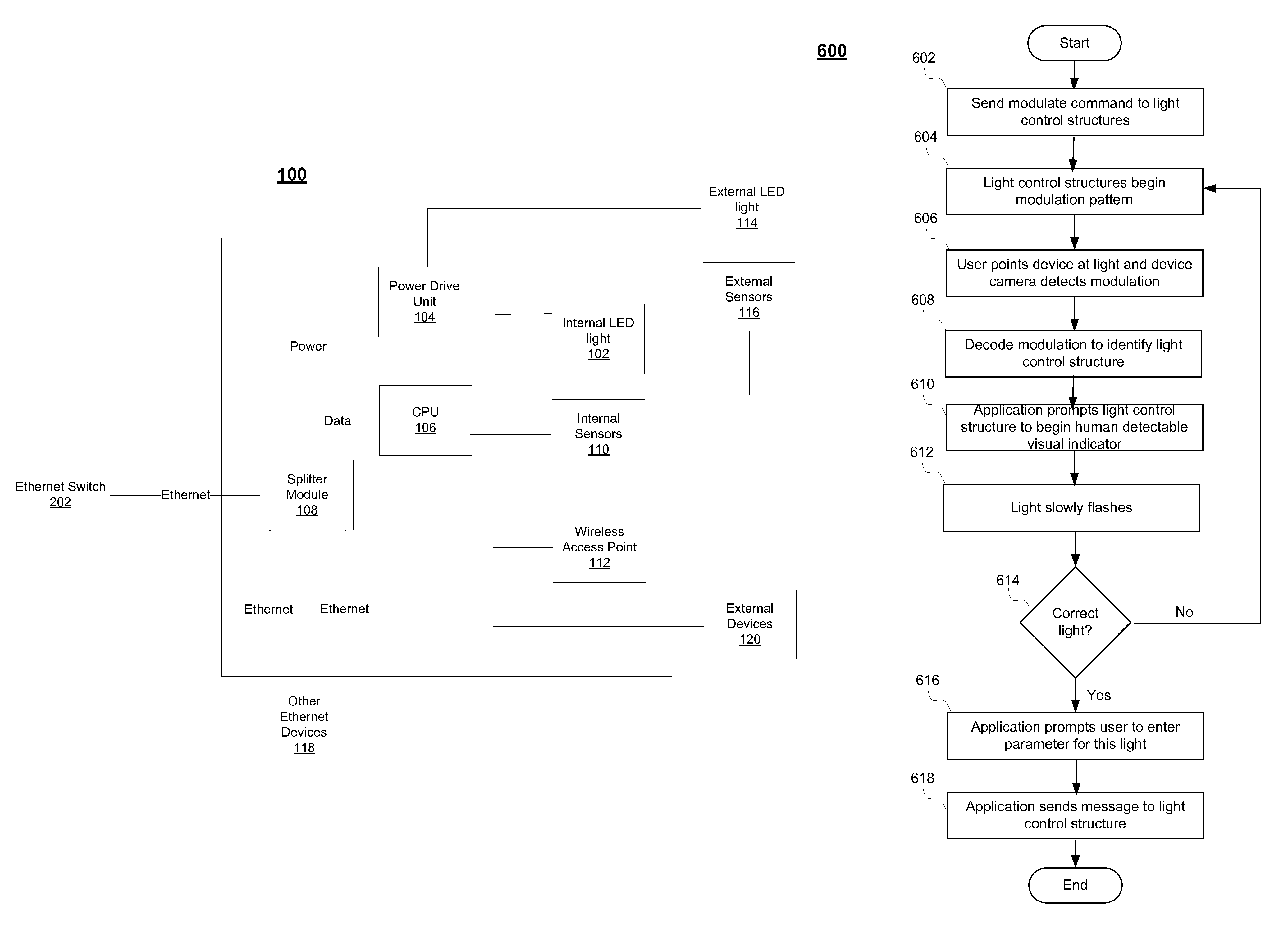
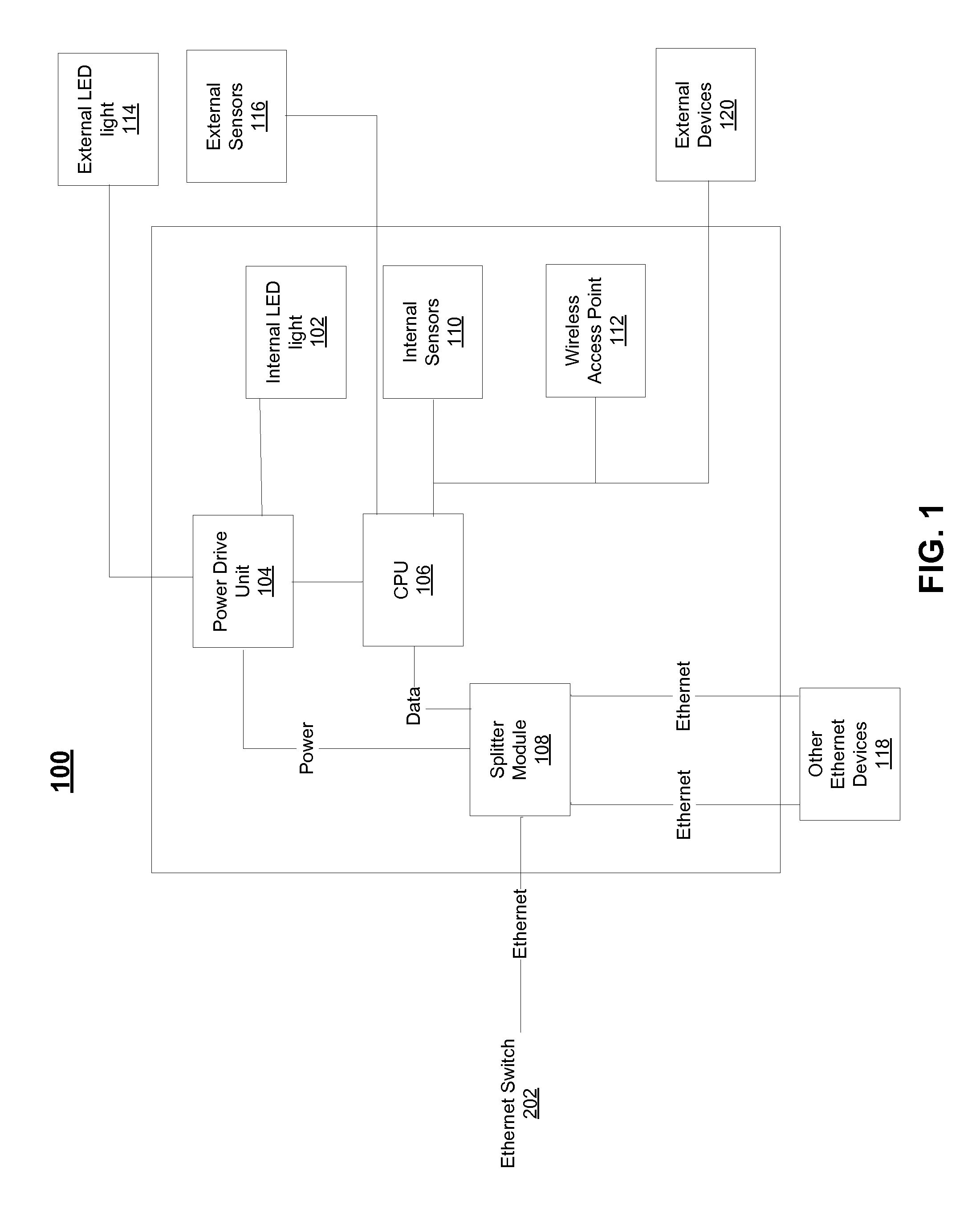
[0021]FIG. 1 is a block diagram showing an exemplary light control structure 100 (also referred to as a light control module) that may be connected to an Ethernet cable. The light control structure 100 may optionally comprise a power drive unit 104, a central processing unit (CPU) 106, a splitter module 108, an internal LED light 102, and other components. While one internal LED light 102 is depicted in FIG. 1, any number of internal LED lights may be optionally affixed to the light control structure 100. One or more external lights 114 may also be utilized in the system and controlled by the light control structure 100. The external lights 114 may be used in conjunction with, or in place of, internal lights 102. The LED lights 102, 114 may be any type of standard LED light commercially available. Each LED light 102, 114 may comprise one or more individual lights.

[0022]Typically LED lights range from 1 watt to 25 watts (corresponding to the light output of incandescent bulbs of many...


PUM


Abstract

A system, method, and computer program for deploying a lighting system throughout a building using power over Ethernet is provided. In exemplary embodiments, one or more LED lighting structures may be powered using Ethernet cable in a building, and may be controlled by a distributed management system throughout a communication network.

Description

BACKGROUND[0001]1. Field of the Invention[0002]The present invention is generally related to systems and methods for a building lighting system that is powered using Power over Ethernet.[0003]2. Related Art[0004]Presently, many buildings have complicated electrical wiring systems that are installed when the building is first built. These wiring systems are typically required to be installed by a certified electrician, and the placement of overhead lighting and electrical outlets is predetermined by the wiring system that is pre-installed in the building. After the building is built, adding or moving light fixtures may be complicated and costly, requiring substantial re-wiring by an electrician.[0005]Each light in a building may also be connected to a light switch module that is used for turning it on and off. The placement of this switch is also pre-determined by the electrical wiring system when the building is first built. Moving the placement of the light switch modules, or alter...

Claims


Application Information

Patent Timeline
Patent Type & Authority Patents(United States)
IPC IPC(8): H05B37/02H05B44/00
CPCH05B37/0263H05B37/02H05B37/0227H05B37/0254H05B47/18H05B47/105H05B47/19H05B47/125H05B47/165H05B45/10H05B45/22H05B47/185
Inventor HUGHES, DAVID ANTHONYHUGHES, MICHAEL RAYMOND
Owner HUGHES DAVID ANTHONY
Why Eureka
Try Eureka