Replaceable ductile fuse

a ductile fuse and replacement technology, applied in protective buildings/shelters, building types, construction, etc., can solve the problems of time-consuming and cost-intensive replacement of anchor rods, and the implementation of techniques may be costly and time-consuming, so as to achieve little or no downtime for the structure

Active Publication Date: 2015-10-13
BURNS & MCDONNELL ENG
View PDF30 Cites 4 Cited by
  • Summary
  • Abstract
  • Description
  • Claims
  • Application Information

AI Technical Summary

Benefits of technology

[0011]The designer of a structure preferably may use the fuse to couple the structure to a concrete embedded anchor in such a way that the connection between the structure and anchor satisfies the requirements of the American Concrete Institute's Building Code Requirements for Structural Concrete (ACI 318) and in particular the seismic design requirements therein. The fuse is configured so that it deforms in a ductile manner when a predetermined amount of force is exerted on the fuse by the structure. After the fuse deforms, the deformation is visual, and the fuse may be removed and replaced without costly modifications to the structure, anchor, and concrete and with little or no downtime for the structure. The fuse provides a simple method of dictating a ductile failure limit state on a connection, especially when implemented in a moderate to high seismic zone where a ductile failure is mandated by current building codes.

Problems solved by technology

After the anchor rod fails, however, it is costly and time-consuming to replace the anchor rod.
These techniques, however, may be costly and time-consuming to implement.

Method used


Image

  • Replaceable ductile fuse
  • Replaceable ductile fuse
  • Replaceable ductile fuse

Examples


Embodiment Construction

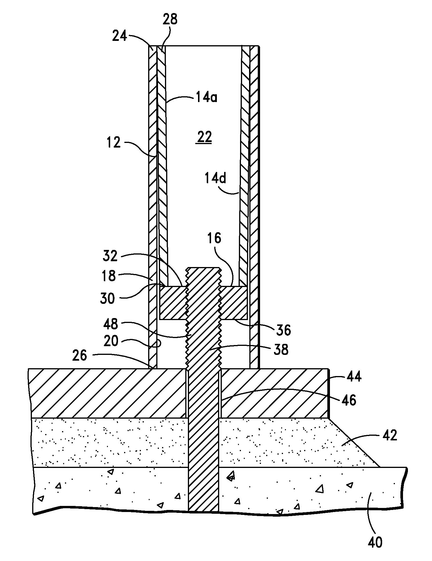
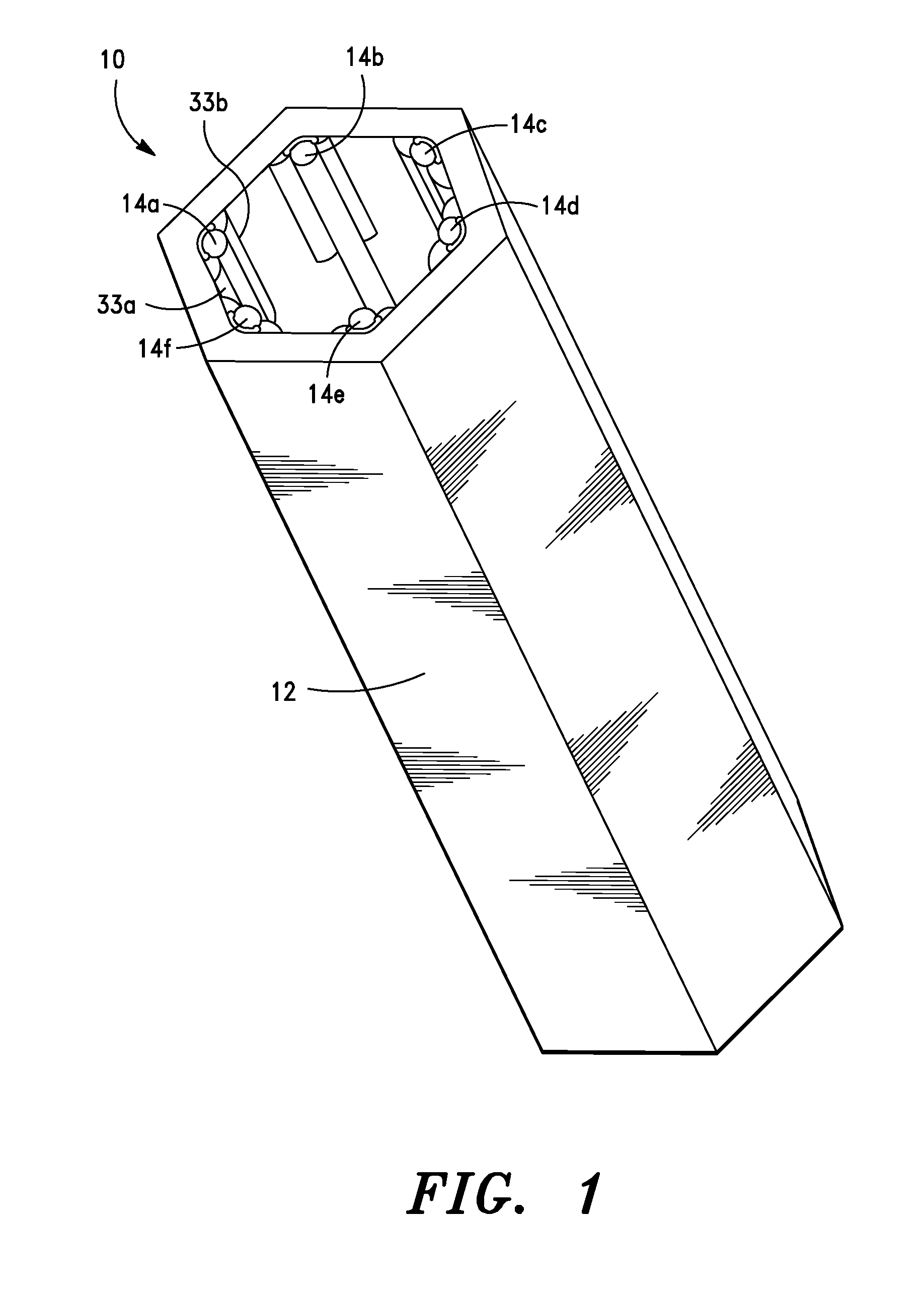
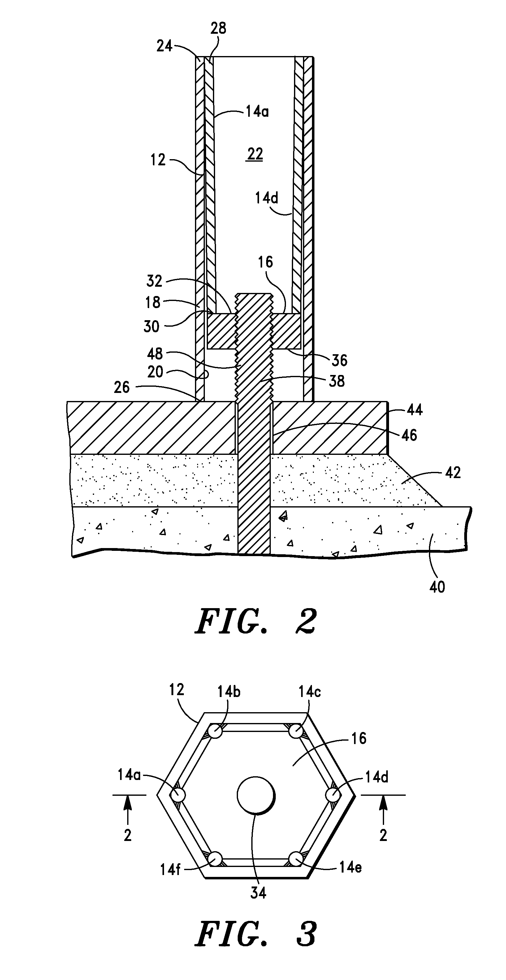
[0031]Referring to FIG. 1, a fuse assembly in accordance with one embodiment of the present invention is identified generally as 10. Fuse assembly 10 is designed to engage the threads of an anchor bolt, which is preferably partially embedded in concrete, to secure a portion of a structure, such as a column base plate, to the anchor bolt. Fuse assembly 10 includes at least one fuse that is positioned in the load path between the structure and the anchor bolt. The fuse is configured to deform in a ductile manner when the structure is subjected to a load exceeding the rated threshold of the fuse, which causes a stress in the fuse exceeding an elastic limit of the fuse. The fuse is designed to be an intentional weak link in the load path between the structure and the anchor bolt so that the fuse will deform in a ductile manner before the structure, anchor bolt, and concrete embedding the anchor bolt are damaged. After the fuse deforms in a ductile manner, fuse assembly 10 may be disenga...


PUM


Abstract

A fuse and a method of using the fuse to removably couple a structure to an anchor preferably partially embedded in concrete. The fuse is configured to be removably coupled to the anchor so that the fuse is positioned in a load path between the anchor and the structure. The fuse is configured to deform in a ductile manner when the structure exerts a force on the fuse that causes a stress in the fuse which exceeds an elastic limit of the fuse. The fuse may be decoupled from the anchor without altering the concrete, the anchor, and the structure. If the structure exerts a force on the fuse that causes the fuse to deform in a ductile manner, the fuse may be decoupled from the anchor and replaced with another fuse.

Description

CROSS-REFERENCE TO RELATED APPLICATIONS[0001]This application is based on and claims priority to U.S. Provisional Application Ser. No. 61 / 903,534, filed on Nov. 13, 2013, which is incorporated herein by reference in its entirety.STATEMENT REGARDING FEDERALLY SPONSORED RESEARCH OR DEVELOPMENT[0002]Not applicable.BACKGROUND OF THE INVENTION[0003]1. Field of the Invention[0004]The present invention is directed to a replaceable ductile fuse, and in particular, to a replaceable ductile fuse configured to be positioned in the load path between an anchor preferably partially embedded in concrete and a structure.[0005]2. Description of Related Art[0006]Structural elements, such as a building column, are commonly joined to a supporting concrete foundation with an anchor that is partially embedded in the concrete and coupled to the structural element. In the case of a building column, the column may have a baseplate with an opening that receives a portion of the anchor. A nut may be threaded ...

Claims


Application Information

Patent Timeline
Patent Type & Authority Patents(United States)
IPC IPC(8): E04H9/02E04B1/38E04B1/92
CPCE04H9/027E04B1/92E04B1/38E04H9/021
Inventor NEWMAN, NATHAN G.HEFFERN, KEVIN P.
Owner BURNS & MCDONNELL ENG
Why Eureka
Try Eureka