Firearm rail assembly

a technology for rails and firearms, applied in the field of modular rails, can solve the problems of not providing configurable or interchangeable features akin to the desirable features of modular weapons platforms, and achieve the effects of facilitating flexing or relative movement, facilitating recoil and other force containment, and providing additional configurability to weapons platforms

Active Publication Date: 2015-10-13
CADEX
View PDF41 Cites 44 Cited by
  • Summary
  • Abstract
  • Description
  • Claims
  • Application Information

AI Technical Summary

Benefits of technology

[0006]The modular rail assembly includes at least an aft rail preferably positioned above the receiver, and a fore rail preferably positioned above the foretube, which cooperate with one another to enable a modular system whereby one rail may be removed or replaced without affecting the other rail and any accessories mounted thereon. For example, a scope may be mounted on the aft rail and the fore rail may be removed or replaced with another fore rail without affecting the scope. That is, the scope is not removed and, therefore, will remain properly positioned or “zeroed”. In the case of prior art rail systems, the entire rail would be removed and the scope would then need to be “rezeroed”. Similarly, other portions of the modular weapons platform such as the action, the barrel, the buttstock, etc., may be removed without necessarily impacting each of the rails of the rail assembly. The novel configuration of the fore and aft rails and the cooperation between the rails results in advantageous recoil and other force containment. While not intending to be bound by any particular theory, the two-piece (or more) design described herein provides a discontinuous surface wherein dissipation of recoil or other forces is interrupted or lessened by the modular configuration of the rail assembly. With a single rail, these forces dissipate along the entire length of the rail, thereby possible impacting accessories mounted thereon. The novel use of a modular connection between the fore and aft rails according to the present invention provides a break between the rails which facilitates flexing or relative movement of one rail relative to the other due, at least in part, to tolerances there between.
[0007]Moreover, the ability to remove only one rail, that is, a portion of the rail assembly, provides additional configurability to the weapons platform. For example, if the fore rail is removed, portions of the weapons platform may be removed without affecting the aft rail or any accessories, such as a scope, mounted thereon. The novel configuration of the rail assembly according to the present invention also enables the weapons platform to be used with foretubes (through which the barrel extends) of varying lengths. Another exemplary benefit is that other portions of the weapons platform, such as the receiver and the barrel, may be removed without removing one of the rails leaving all accessories mounted thereon in position. Alternatively, one rail of the rail assembly may be substantially permanently affixed (that is, not intended to be readily removed) to or be integral to a portion of the weapons platform, for example the receiver, and the modularity is achieved by providing a modular additional rail, for example a fore rail, that cooperates with the permanently affixed rail.

Problems solved by technology

Although a single rail assembly effectively achieves its intended purposes, such as effective accessory mounting for a modular weapons platform, it does not provide configurable or interchangeable features akin to the desirable features of the modular weapons platform upon which it is mounted.

Method used


Image

  • Firearm rail assembly
  • Firearm rail assembly
  • Firearm rail assembly

Examples


Embodiment Construction

[0025]The present invention will be described in detail with reference to the accompanying drawings. It is to be understood, however, that this invention is not limited to the specific systems, devices, and / or methods disclosed unless otherwise specified, as such can, of course, vary. It is also to be understood that the terminology used herein is for the purpose of describing particular aspects only and is not intended to be limiting. Thus, the following description is provided as illustrative of the principles of the present invention and not in limitation thereof.

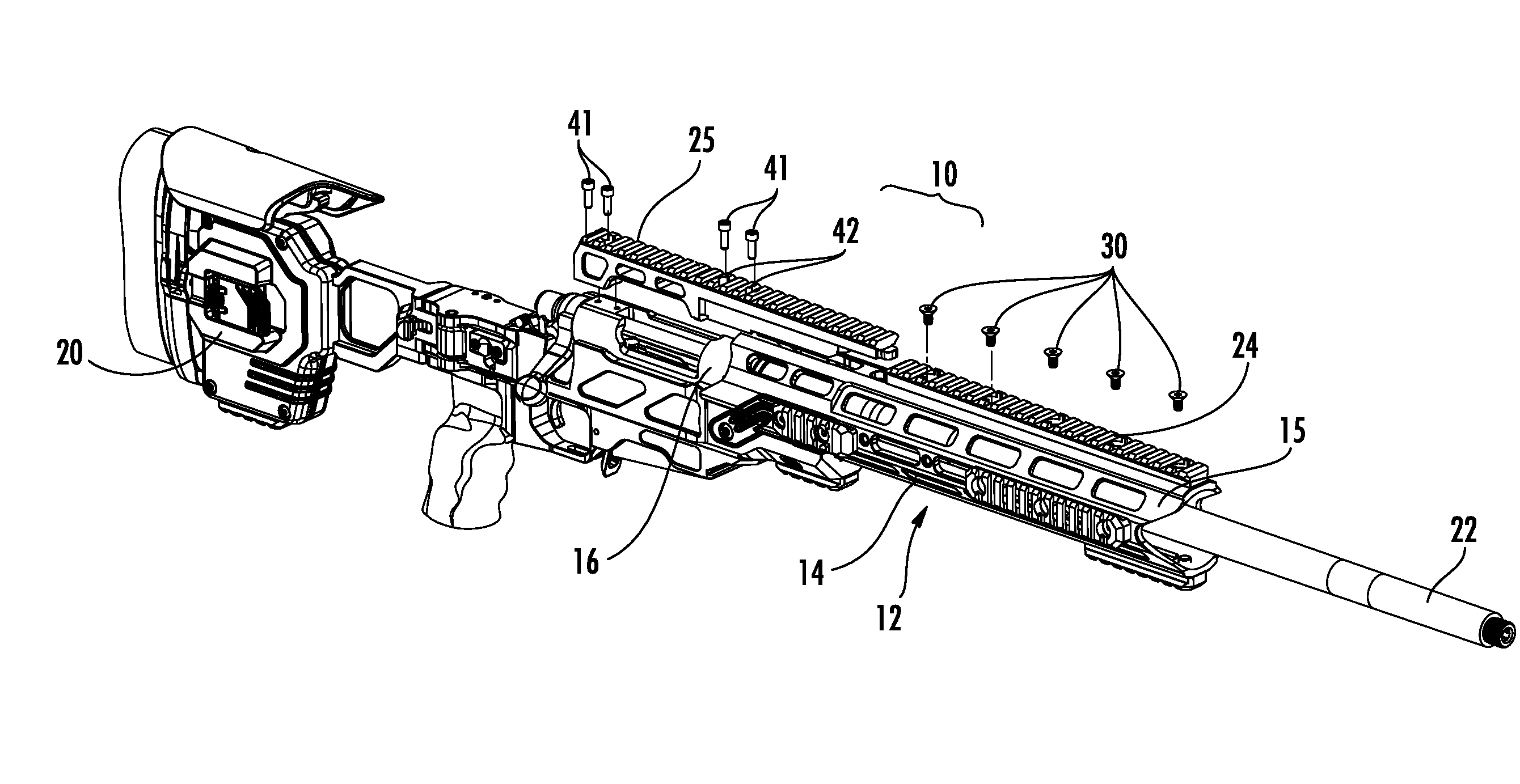
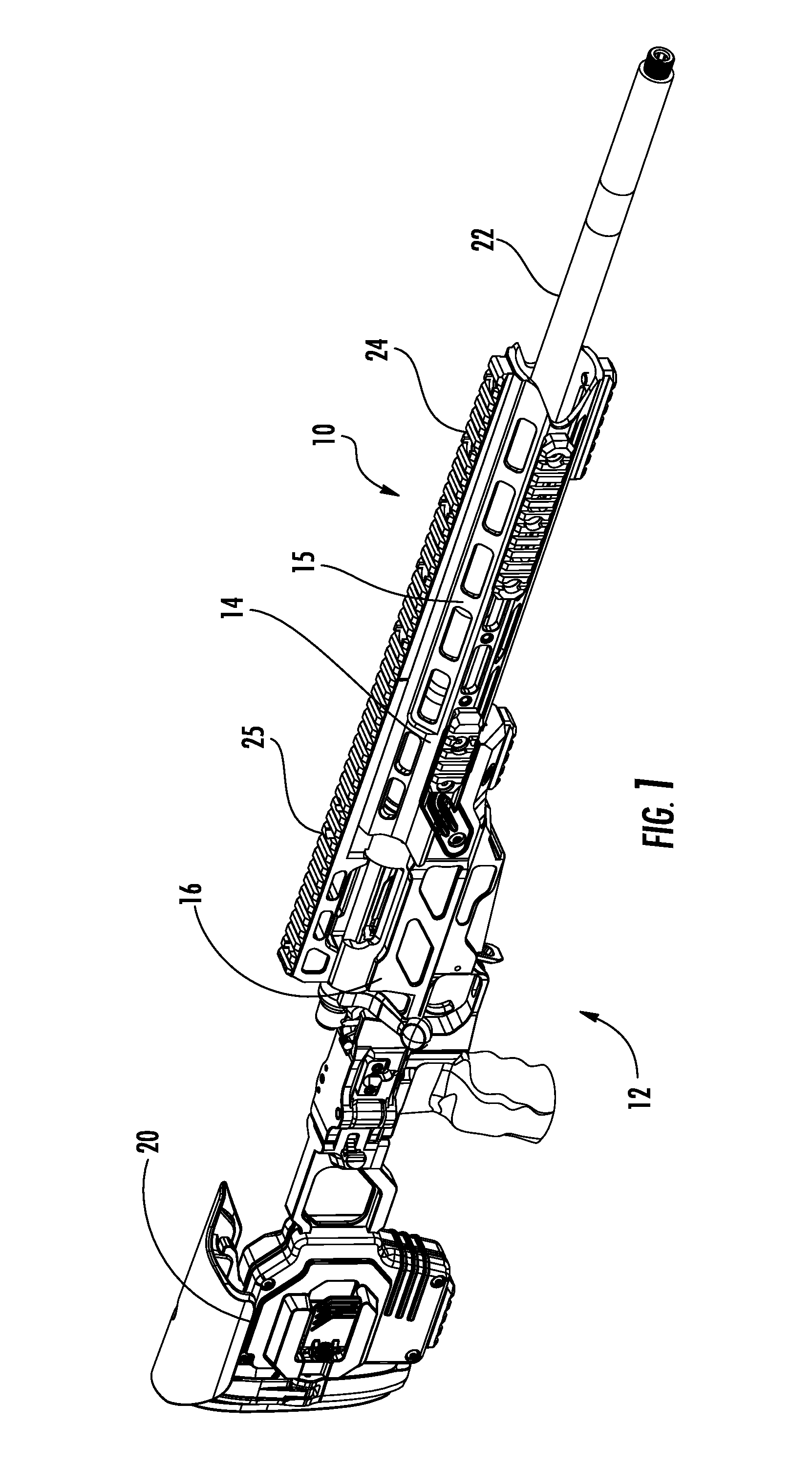
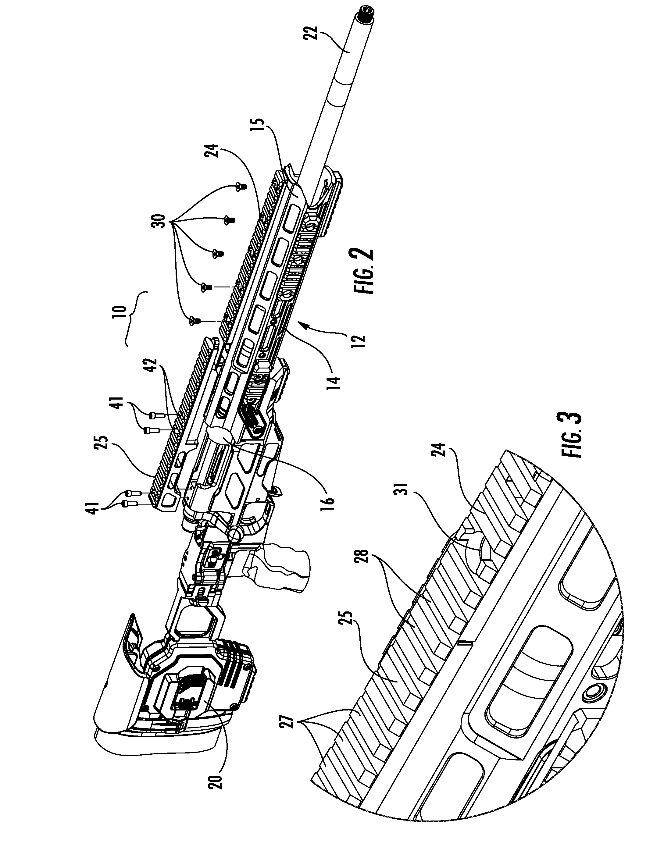
[0026]FIG. 1 illustrates the modular rail assembly 10 secured to the modular weapons platform 12 and FIG. 2 illustrates an exploded view of the modular rail assembly 10 juxtapositioned above the modular weapons platform 12. The modular weapons platform 12 includes a forestock assembly 14, including the foretube 15. The central receiver assembly 16 includes various components including a receiver, bolt action, trigger, an...


PUM


Abstract

A modular rail assembly for supporting accessories upon a modular weapons platform. The modular rail assembly includes a fore rail preferably positioned above the foretube, and an aft rail preferably positioned above the receiver, which cooperate with one another to enable a modular system whereby one rail may be removed or replaced without affecting the other rail and any accessories mounted thereon. One rail defines a mating member and the other rail defines a mating channel for receipt of the mating member. The rail assembly configuration provides increased flexibility and interchangeability to the modular weapons platform.

Description

CROSS REFERENCE TO RELATED APPLICATIONS[0001]This application claims the benefit of U.S. Provisional Patent App. Ser. No. 61 / 781,922 filed Mar. 14, 2013.FIELD OF THE INVENTION[0002]The present disclosure relates generally to firearms, and more particularly to a modular rail assembly for cooperating with a firearm to support mounted firearm accessories.BACKGROUND OF THE INVENTION[0003]Modern firearms, including those employed in military and law enforcement applications, often include various accessories to assist the shooter. Such devices may be mounted directly to the firearm or indirectly on a mount associated with the firearm. Conventional mounts include securing accessories to the firearm with a Picatinny rail. A Picatinny rail is a bracket used on firearms in order to provide a standardized mounting platform for accessories and attachments, such as scopes. These rails generally include a single rail extending along the upper surface of the firearm and typically extend at least ...

Claims


Application Information

Patent Timeline
Patent Type & Authority Patents(United States)
IPC IPC(8): F41C23/16F41G11/00F41A3/66
CPCF41C23/16F41G11/003F41A3/66
Inventor DEXTRAZE, SERGE
Owner CADEX
Why Eureka
Try Eureka