Bone plate system for osteosynthesis

a bone plate and osteosynthesis technology, applied in the field of bone plate system for osteosynthesis, can solve the problems of lack of plate system options, lack of option for drawing bone fragments to the bone plate, etc., and achieve the effects of increasing angular stability, increasing angular stability, and certain angular stability

Inactive Publication Date: 2015-10-20
MERETE MEDICAL
View PDF113 Cites 45 Cited by
  • Summary
  • Abstract
  • Description
  • Claims
  • Application Information

AI Technical Summary

Benefits of technology

[0010]The object of the invention is to provide new technologies in the field of bone plate systems for osteosynthesis, which bone plate systems can be flexibly employed by the user and have enhanced practicality in use and optimized angular stability for the bone screws.

Problems solved by technology

A disadvantage of known fixed-angle bone plate systems is the lack of an option for drawing bone fragments to the bone plate during the process of tightening, since, due to its thread on the screw head, the thread of the screw head locks up in the bone plate during the last rotation.
Moreover, for weakened osteoporotic bones there is a lack of plate systems with options for fixing a plurality of screws to or in a bone plate at a fixed angle in a narrow space.

Method used


Image

  • Bone plate system for osteosynthesis
  • Bone plate system for osteosynthesis
  • Bone plate system for osteosynthesis

Examples


Embodiment Construction

[0050]The invention shall be described in greater detail in the following using preferred exemplary embodiments, referring to figures.

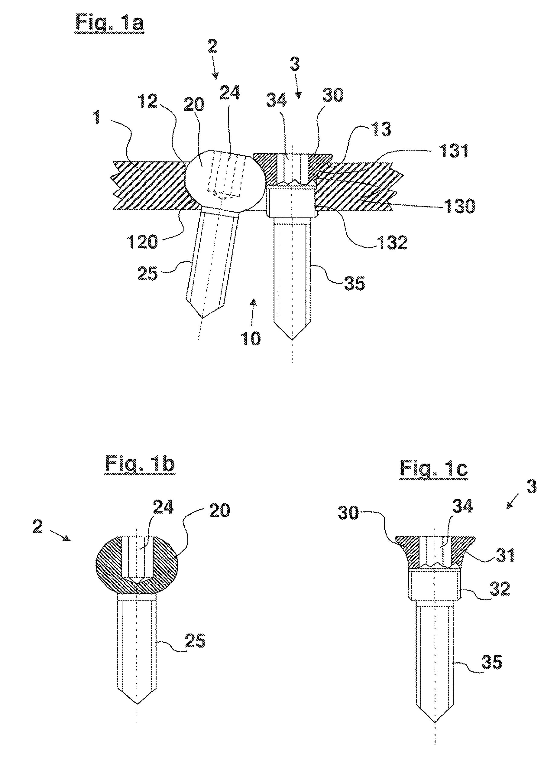
[0051]FIG. 1a is a longitudinal section through a bone plate system having a bone plate, a swivel screw, and a clamping screw;

[0052]FIG. 1b is a longitudinal section through the swivel screw from FIG. 1a;

[0053]FIG. 1c is a longitudinal section through the clamping screw from FIG. 1a;

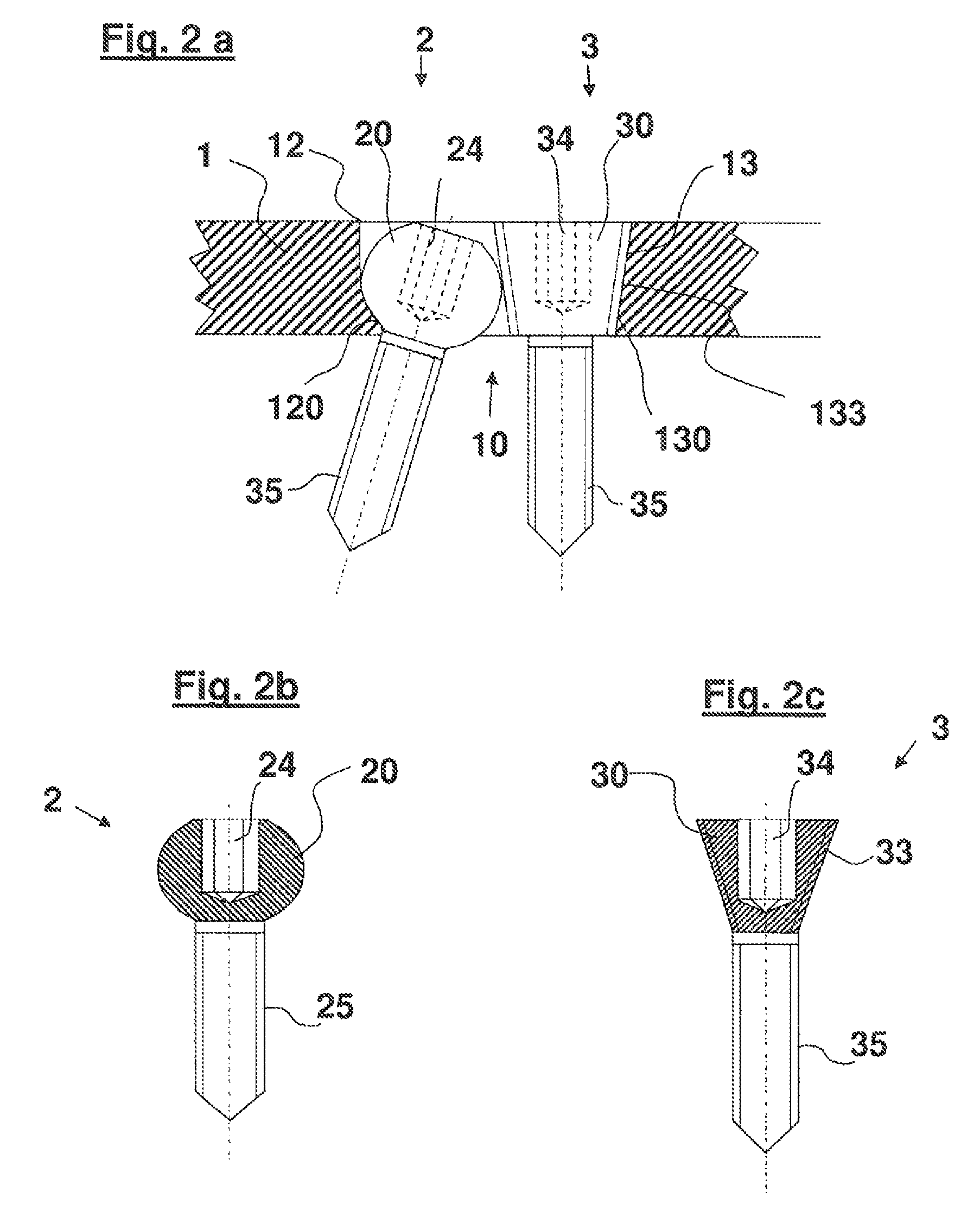
[0054]FIG. 2a is a longitudinal section through a bone plate system having a bone plate, a swivel screw, and a clamping screw in accordance with a further embodiment;

[0055]FIG. 2b is a longitudinal section through the swivel screw from FIG. 2a;

[0056]FIG. 2c is a longitudinal section through the clamping screw from FIG. 2a;

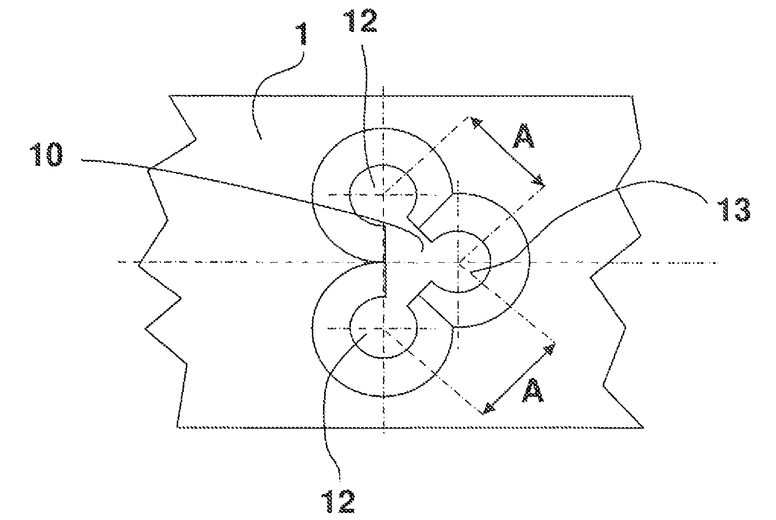
[0057]FIG. 3a is a top view onto a bone plate having a plate hole group;

[0058]FIG. 3b is a top view onto a bone plate having a plate hole group in accordance with a further embodiment;

[0059]FIG. 3c is a modification of the bone plate from FIG. 3b;

[00...


PUM


Abstract

A bone plate system for osteosynthesis comprises a bone plate, a swivel screw, a clamping screw, a swivel hole formed in the bone plate as a through hole for receiving the swivel screw polyaxially, and a clamping hole, which is associated with the swivel hole and is formed in the bone plate as a further through hole for receiving the clamping screw. When the swivel screw and the clamping screw are screwed in, they are fixed with angular stability in multiple dimensions, as the screw heads of the swivel screw and of the clamping screw are secured by one another and by the bone plate against relative movement. The swivel screw and the clamping screw are each designed as a bone screw.

Description

CROSS-REFERENCE TO RELATED APPLICATIONS[0001]This application is the U.S. national stage application of International Application No. PCT / DE2010 / 075167, filed Dec. 21, 2010, which International application was published on Jun. 30, 2011 as International Publication No. WO 2011 / 076205 A1 in the German language and which application is incorporated herein by reference. The International application claims priority of German Patent Application No. 10 2009 060 396.4, filed Dec. 22, 2009, and German Patent Application No. 20 2010 005 260.2, filed Apr. 20, 2010, which applications are incorporated herein by reference.[0002]The invention relates to technologies in the field of bone plate systems for osteosynthesis.BACKGROUND OF THE INVENTION[0003]Bone plate systems provide fixed-angle fixation of a bone plate by means of assigned screws for osteosynthesis in the human or animal body. Numerous bone plate systems are known that generally include a bone plate with an arrangement of a pluralit...

Claims


Application Information

Patent Timeline
Patent Type & Authority Patents(United States)
IPC IPC(8): A61B17/80A61B17/86
CPCA61B17/863A61B17/8033A61B17/8038A61B17/8042A61B17/8057A61B17/8605
Inventor CLASBRUMMEL, BERNHARDKRANZ, CURT
Owner MERETE MEDICAL
Why Eureka
Try Eureka