
Blink actuation mechanism for a prosthetic eye

a technology of prosthetic eyes and actuators, applied in the field of prosthetic eyes, can solve the problems of facial paralysis, immobile and thus not real lifelike, loss of eyelids or entire eye sockets, etc., and achieve the effect of convenient patient inserting and hygieni

Inactive Publication Date: 2015-10-20
ALTMAN STUART MAXWELL +3
View PDF7 Cites 6 Cited by
  • Summary
  • Abstract
  • Description
  • Claims
  • Application Information

AI Technical Summary

Benefits of technology

This patent describes a device that is used to treat glaucoma. The device contains a metal tarsus, which is attached to a motor and designed to mimic a piece of human tissue. The metal tarsus helps to provide rigidity and allows the eye to blink. The device is protected by polyurethane foam and is easy to insert for patients. The technical effect of this device is that it helps to manage glaucoma by regulating the pressure in the eye.

Problems solved by technology

One possible facial defect is the loss of an eyelid or entire eye socket.
While current orbital prostheses are able to replace absent facial anatomies with artificial eyes and eyelids, they are immobile and thus not truly lifelike.
Although these prostheses are the current gold standard in protecting sensitive skin against outside stimuli while mimicking the appearance of the healthy eye, they are immobile and at best create an appearance of facial paralysis.
Facial paralysis and other forms of facial disfigurement attract attention and can lead to greater levels of anxiety, depression, maladaptive behavior, and reduced emotional well-being [1].
Orbital prosthesis that are static are not successful in fully overcoming the appearance of abnormality and reducing the associated psychological distress.
Although these types of orbital prosthesis appear lifelike, they do not have a blinking capability.
Thus, individuals using the prosthesis can be perceived as abnormal as they are unable to blink with their orbital prosthesis.
Because the orbital prosthesis does not blink, patients become prone to daily psychological trauma in addition to suffering from a loss of facial function.

Method used


Image

  • Blink actuation mechanism for a prosthetic eye
  • Blink actuation mechanism for a prosthetic eye
  • Blink actuation mechanism for a prosthetic eye

Examples


Embodiment Construction

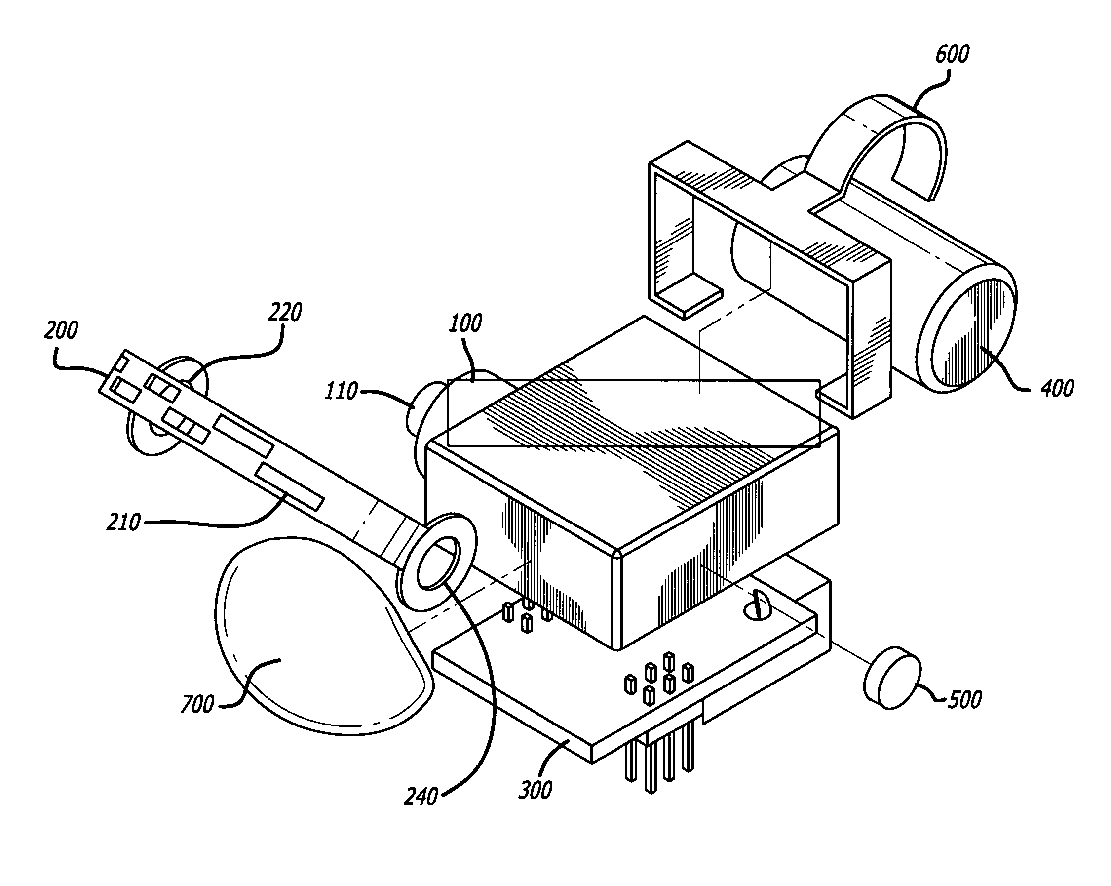
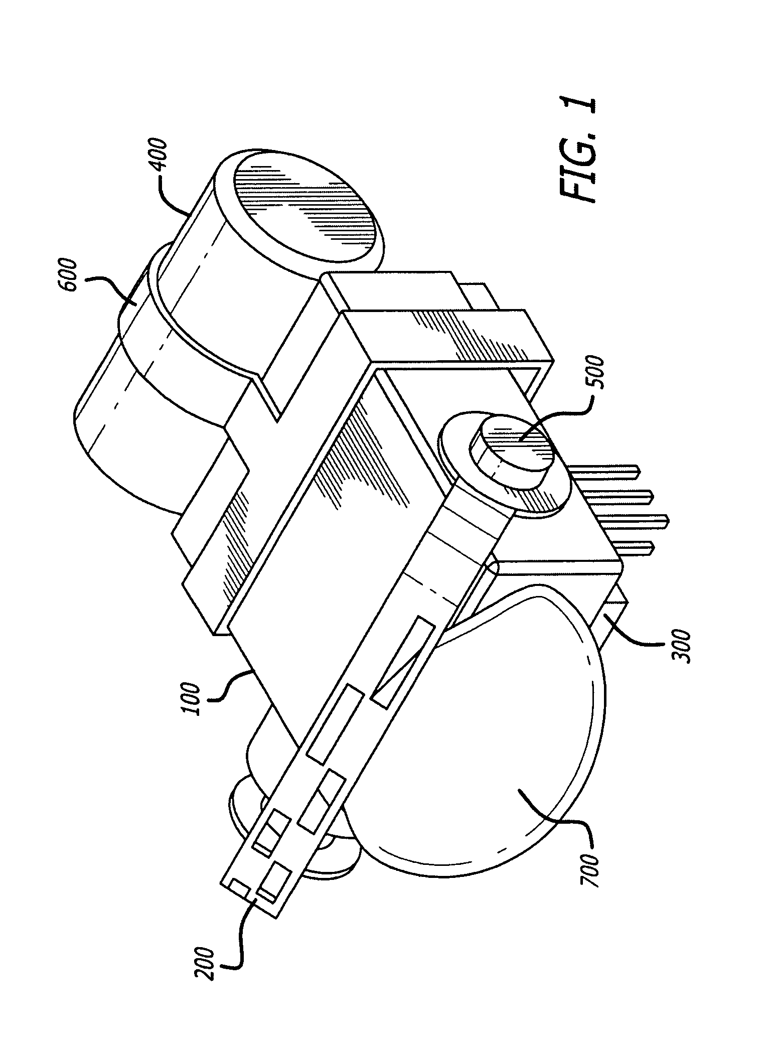
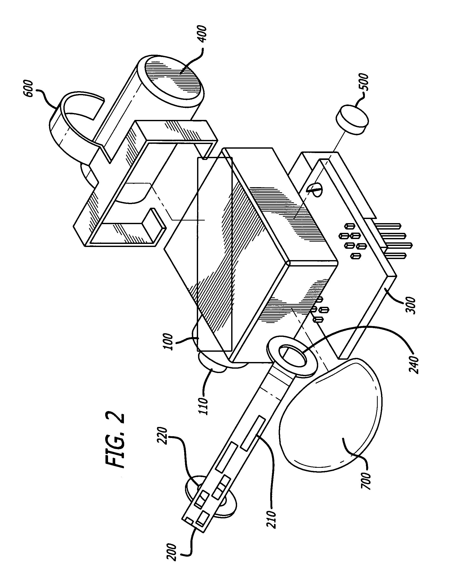
[0025]FIGS. 1 through 4 illustrate an exemplary embodiment of the disclosed orbital prosthesis assembly in perspective, perspective exploded and side views.

[0026]FIG. 2 shows a perspective exploded view. The shown exemplary embodiment of the system includes a Power HD-1705MG Servo Motor 100 manufactured by Pololu, located at 920 Pilot Road, Las Vegas, Nev., 1-877-7-POLOLU, and on the Internet at www.pololu.com. The Pololu product number is 2143. One side of the Servo Motor contains an Output Shaft 110. It is important to understand that the present invention is not limited to the specific motor or type of motor disclosed since various changes and modifications may be effected herein without departing from the scope of the appended claims.

[0027]The Servo Motor 100 is connected to the stainless steel Tarsus 200 through Output Shaft 110. Stainless steel Tarsus contains Drive Hole 220 on one end of Tarsus 200. Tarsus 200 is preferably manufactured from stainless steel. A standard screw,...


PUM


Abstract

The invention relates to a mechanism that can be integrated with silicon facial prostheses used to recapitulate a natural facial appearance through biomimetic actuation. The prosthetic eye comprises a servo motor, microcontroller, battery, rotational shaft, and customized stainless steel tarsus. The tarsus mimics the natural eyelid and reinforces the silicon lid for rotational blink motion. A stainless steel clip holds the device together and polyurethane foam encases the device to allow proper fitting in the orbital cavity. The present invention fits within a model orbital cavity and the generated blink motion is tunable to match the position profile of an in vivo blink.

Description

PRIORITY CLAIMS[0001]The present application claims a priority benefit of U.S. Provisional Patent Application Ser. No. 61 / 835,473, filed Jun. 14, 2013, entitled “Prosthetic Eye.” The foregoing disclosures are expressly incorporated herein by reference to the same extent as if set forth verbatim herein and shall be fully and completely a part of this document.BACKGROUND OF THE INVENTION[0002]1. Field of the Invention[0003]The present disclosure relates to the field of prosthetic devices. More specifically, the invention relates to a prosthetic eye with a natural blink. Even more specifically, the present disclosure relates to a mechanism integrable into a prosthetic eye that effectuates a normal blink which provides a normal facial appearance for people with facial defects.[0004]2. Description of the Related Art[0005]Facial defects can be caused by congenital anomalies, trauma, or cancer. One possible facial defect is the loss of an eyelid or entire eye socket. The treatment is an or...

Claims


Application Information

Patent Timeline
IPC IPC(8): A61F2/16A61F2/14
CPCA61F2/141
Inventor ALTMAN, STUART MAXWELLBRODERICK, CATHERINE GRACECAFFREY, ELISMAROND, DANIELLE SHEREE
Owner ALTMAN STUART MAXWELL
Learn More