Flaring device for a tubular member

a tubular member and flaring device technology, applied in the field of flaring devices for tubular members, can solve the problems of inconvenient operation of the flaring device, laborious and tardy, non-uniform expansion, etc., and achieve the effects of convenient detachment, operation or replacement, and improved flaring efficiency

Active Publication Date: 2015-10-20
CHENG CHIEH YU
View PDF3 Cites 8 Cited by
  • Summary
  • Abstract
  • Description
  • Claims
  • Application Information

AI Technical Summary

Benefits of technology

[0009]An object of the present invention is to provide a flaring device for a tubular member, in which the flaring device could provide a proper handle length for a user to operate or effort easily so as to get a better flaring efficiency. Furthermore, the flaring device is convenient for the user to detach, replacement, repair, produce and store. Moreover, the flaring device could prevent a flaring portion of the tubular member from non-uniformly being flared for avoiding an irregularly flaring result. Thus, the flaring device could provide variable flaring sizes for the tubular member, or / and selectively to flare the tubular member gradually.

Problems solved by technology

However, the conventional flaring device is inconveniently to operate, and said rotation of the screw rod for the two conical clipping members to approach to or be away from each other, is laborious and tardy.
Therefore, the two conical surfaces rotated relative to each other would apply a torsion onto the two expanders to cause a non-uniform expansion.
However, the further conventional flaring device could be only operated by applying a hand press.
Therefore, a flaring efficiency of the further conventional flaring device is bad, and if the tubular member has a thick tubular wall, the thick tubular wall could not be flared.

Method used


Image

  • Flaring device for a tubular member
  • Flaring device for a tubular member
  • Flaring device for a tubular member

Examples


Embodiment Construction

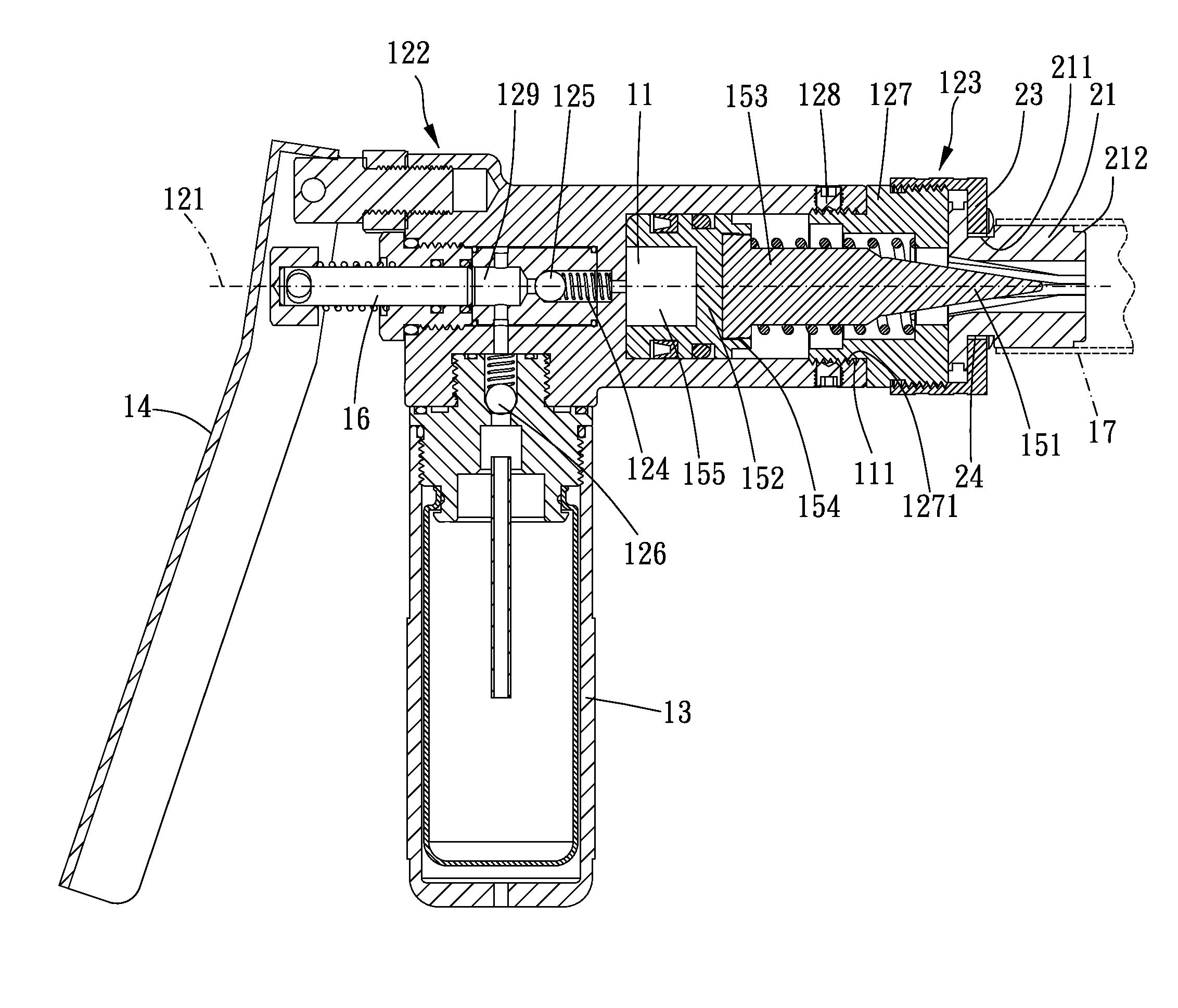
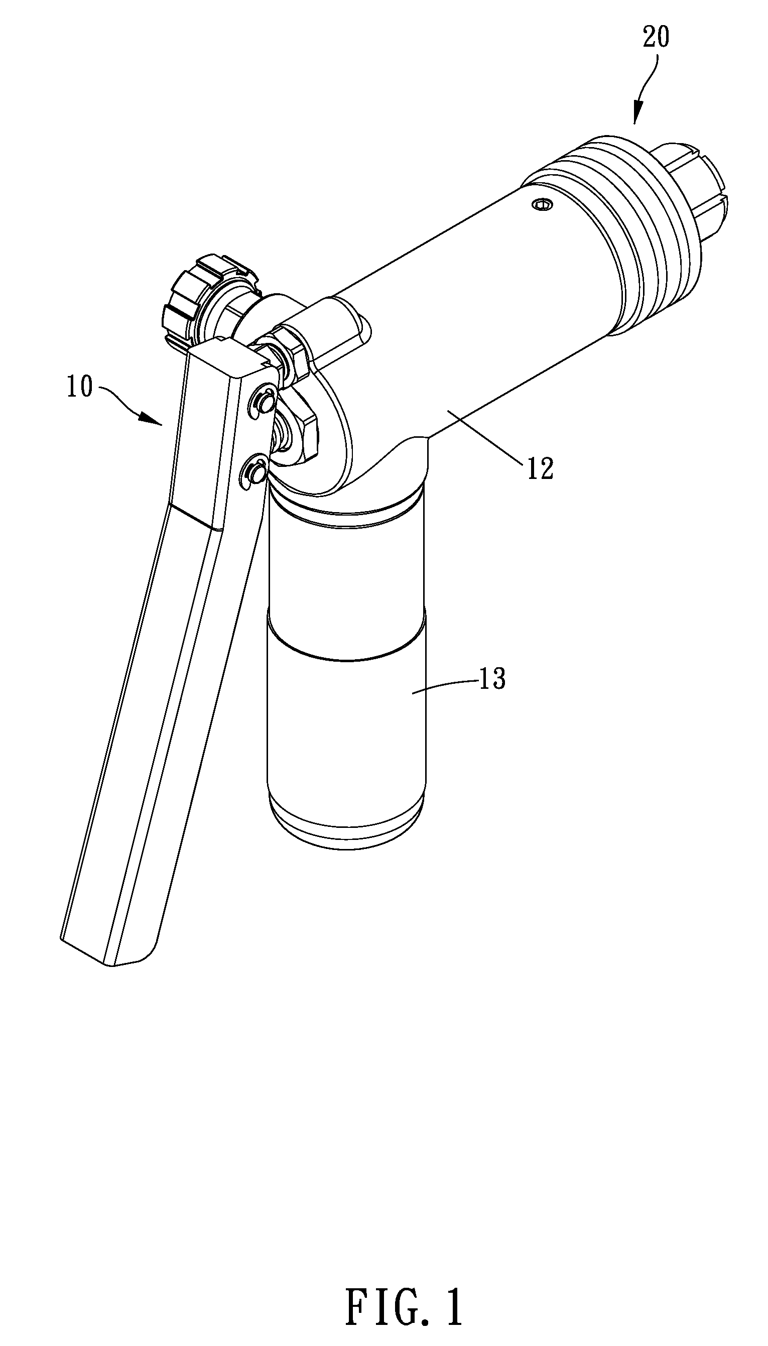
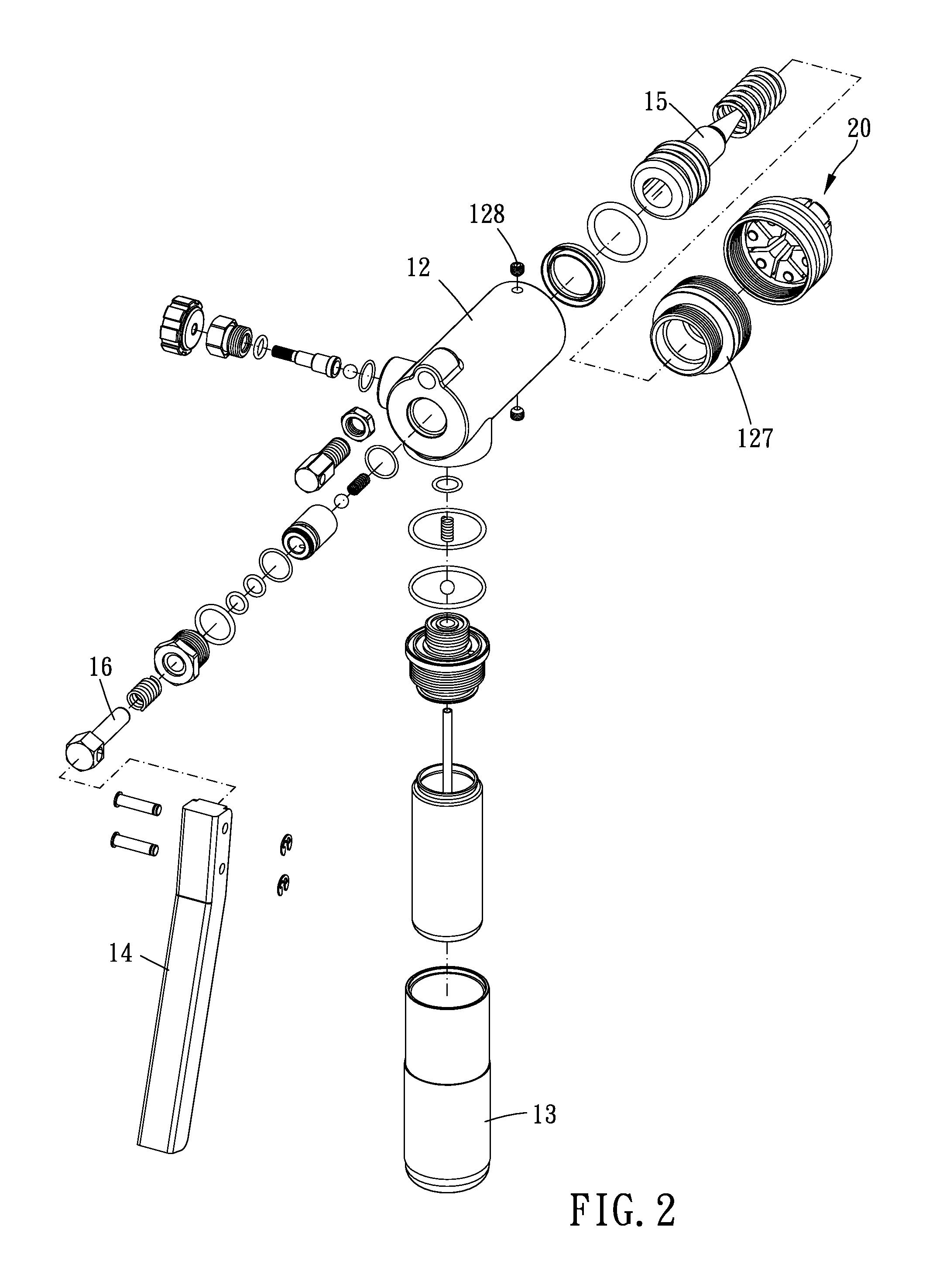
[0021]FIGS. 1-4 show a flaring device according to a preferred embodiment of the present invention. The flaring device is used to flare a hollow malleable tubular member and includes a hydraulically powered assembly 10 and a die set 20.

[0022]The hydraulically powered assembly 10 includes a main body 12 having a cylinder 11, a liquid container 13, a lever 14 and a piston member 15 received in the cylinder 11.

[0023]The main body 12 has an axis 121, a first end 122 and a second end 123. The first end 122 and the second end 123 are located on the axis 121 and are opposite to each other. The liquid container 13 is traverse to a direction in which the axis 121 extends (such as vertical to the axis 121) and radially extended from the main body 12, so that the flaring device could provide a proper hold length for operating with one hand. Clearly, the liquid container 13 controllably communicates with the cylinder 11 in fluid flowing relationship. A fluid passage 124 is formed between the cy...


PUM

PropertyMeasurementUnit
depthaaaaaaaaaa
widthaaaaaaaaaa
distanceaaaaaaaaaa

Abstract

A flaring device for flaring a hollow malleable tubular member is provided. A hydraulically powered assembly includes a main body having a cylinder, a lever and a piston member which is received in the cylinder. The main body has an axis and opposing first end and second end. The lever is pivoted on the first end of the main body and operable to drive the piston member to move along the axis. One end of the piston member is formed with a conical expander. The die set is disposed at the second end of the main body and has a plurality of die elements arranged around the axis. The conical expander of the piston member is actuated to move axially and outwardly so as to radially drive the die elements to flare the hollow malleable tubular member.

Description

BACKGROUND OF THE INVENTION[0001]1. Field of the Invention[0002]The present invention relates to a flaring device for a tubular member.[0003]2. Description of the Prior Art[0004]A conventional flaring device is used to flare one end of a tubular member, so that an opening of the tubular member would be flared and expanded. Thus, the flared tubular members could be connected to each other conveniently.[0005]The conventional flaring device has two opposing conical clipping member disposed thereon. A plurality of expanders is arranged around a periphery of the conical clipping member. A user could operate the conventional flaring device to reduce a distance between the two conical clipping members, so that a conical surface of the conical clipping member would push the expanders to move outwardly for flaring and expanding an internal wall of the tubular member.[0006]Clearly, the conventional flaring device includes a screw rod is movably screwed between the two conical clipping members...

Claims


Application Information

Patent Timeline
Patent Type & Authority Patents(United States)
IPC IPC(8): B21D41/02
CPCB21D41/021
Inventor CHENG, CHIEH-YU
Owner CHENG CHIEH YU
Why Eureka
Try Eureka