Impact forming device and method for local small features on metal thin-walled curved-surface part

Pending Publication Date: 2022-09-29
DALIAN UNIV OF TECH
View PDF0 Cites 0 Cited by
  • Summary
  • Abstract
  • Description
  • Claims
  • Application Information

AI Technical Summary

Problems solved by technology

However, processing production, independent control and matching of an integral forming die and a local small die are difficult.
Moreover, no matter press forming or fluid bulging, quasi-static loads are applied to the plate blank, and the forming speed of the blank is relatively slow, so that significant overall springback is prone to occur, and significant deformations can also occur in the area adjacent to the area where the loads are concentrated, so that the accuracy of the final component is affected.
In addition, when the local small features are formed, because deformation is mainly concentrated in a smaller area and the deformation amount is large, the material is more prone to thinning and cracking, and therefore higher requirements are made for the forming performance of the material.
However, when the local small features are formed, electromagnetic forming requires special large-size equipment and dies, and interference is often formed between the special large-size equipment and dies and the

Method used


Image

  • Impact forming device and method for local small features on metal thin-walled curved-surface part
  • Impact forming device and method for local small features on metal thin-walled curved-surface part
  • Impact forming device and method for local small features on metal thin-walled curved-surface part

Examples


Example

Embodiment I

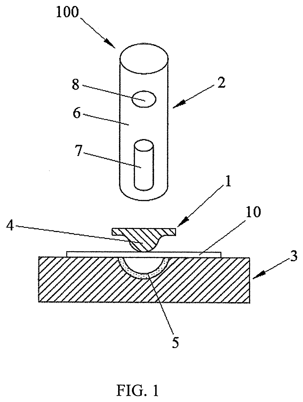
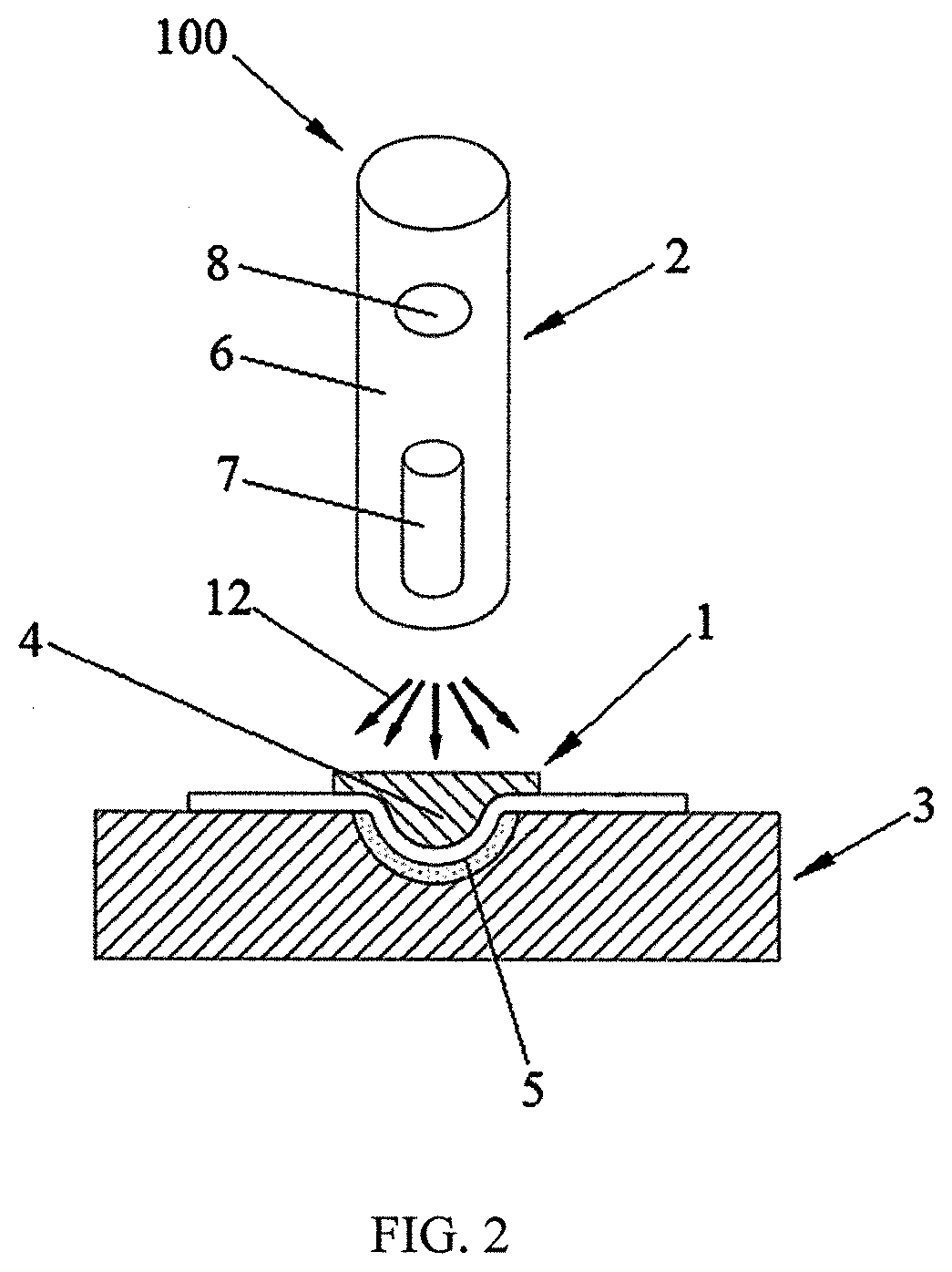
[0046]As shown in FIG. 1 and FIG. 2, the impact forming device 100 for local small features on a metal thin-walled curved-surface part provided by the embodiment comprises impact forming dies 1, impact loading units 2 and a forming supporting die 3, wherein

[0047]the impact forming die 1 is provided with an impact forming part 4, and the impact forming part 4 is a convex part corresponding to a local small feature;

[0048]the forming supporting die 3 can support and fix a metal thin-walled curved-surface part 10 without forming local small features, and the forming supporting die 3 is provided with concave parts 5 matched with the impact forming parts 4; and

[0049]the impact loading unit 2 comprises a guide rail 6, an explosive ball 7 and a detonating block 8, the detonating block 8 and the explosive ball 7 are both arranged in the guide rail 6, the explosive ball 7 can be triggered through the detonating block 8 to apply an instantaneous impact load to the impact forming di...

Example

Embodiment II

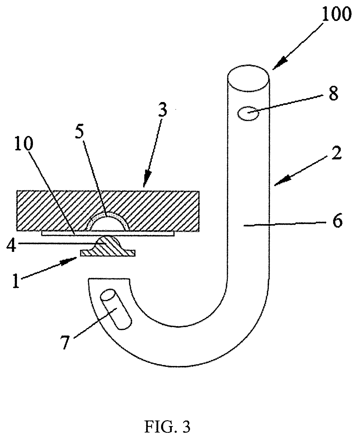
[0053]As shown in FIG. 3 and FIG. 4, the embodiment provides an impact forming device 100 for local small features on a metal thin-walled curved-surface part, and the difference from the first embodiment lies in that the guide rail 6 is arranged to be a linear cylinder, and the detonating block 8 is arranged to be a firing pin. The firing pin can provide initial acceleration by a high-pressure shoot nail device (such as a nail gun). The guide rail 6 is arranged to be a curve cylinder, the steel ball moves in the curve cylinder to fire the explosive ball 7, the fired direction of the explosive ball 7 is inconsistent with the acting direction of the explosive ball 7 applying impact load, and therefore impact loading can be conducted on narrow spaces, the back faces of die tools and shielded parts.

Embodiment III

[0054]As shown in FIG. 5 and FIG. 6, the embodiment provides an impact forming device 100 for local small features on a metal thin-walled curved-surface part, and t...


PUM


Abstract

An impact forming device and method for local small features on a metal thin-walled curved-surface part. The impact forming device includes impact forming dies, impact loading units and a forming supporting die, wherein the impact forming die is provided with an impact forming part, and the impact forming part is a convex part corresponding to a local small feature; the forming supporting die can support and fix a metal thin-walled curved-surface part without forming local small features, and the forming supporting die is provided with concave parts matched with the impact forming parts; and the impact loading unit includes a guide rail, an explosive ball and a detonating block, under the impact loading of the impact loading units, the impact forming parts can impact the metal thin-walled curved-surface part without forming local small features under the matching action of the concave parts to form the local small features.

Description

CROSS REFERENCE TO RELATED APPLICATION(S)[0001]This patent application claims the benefit and priority of Chinese Patent Application No. 202110313372.X, filed on Mar. 24, 2021, the disclosure of which is incorporated by reference herein in its entirety as part of the present application.TECHNICAL FIELD[0002]The present disclosure relates to the technical field of metal thin-walled part forming, and particularly relates to an impact forming device and method for local small features on a metal thin-walled curved-surface part.BACKGROUND ART[0003]Metal thin-walled curved-surface parts are widely applied to aviation, aerospace, automobiles and electronic products, such as aircraft skins, automobile outer covering parts and internal integral B columns, intelligent electronic product metal shells and the like. In order to form a reasonable pneumatic flow field, meet a precise connection relation, obtain artistic modeling and other different purposes, the metal thin-walled curved-surface p...

Claims


Application Information

Patent Timeline
IPC IPC(8): B30B1/00B21D22/02B21D37/12
CPCB30B1/001B21D22/02B21D37/12B21D1/06B21D37/10F42D3/00B21D22/04B21D26/08
Inventor HE, ZHUBINZHU, HAIHUI
Owner DALIAN UNIV OF TECH
Why Eureka
Try Eureka