Planar antenna element and antenna

a technology of antenna elements and antennas, applied in the direction of antennas, basic electric elements, antenna feed intermediates, etc., can solve the problems of unstable signal reception in the uhf band, loss situation in the signal transmission process, and failure to cover the uhf band, etc., to achieve high signal reception quality, simple structure, and convenient production and installation

Active Publication Date: 2021-04-01
SHENZHEN ANTOP TECH
View PDF0 Cites 0 Cited by
  • Summary
  • Abstract
  • Description
  • Claims
  • Application Information

AI Technical Summary

Benefits of technology

[0016]Compared with the prior art, the present invention can obtain some beneficial effects. The planar antenna element and the antenna in the present invention are simple in structure, convenient to produce and install, high in signal reception quality, wide in signal coverage, and can effectively cover the UHF band for more stable signals in the UHF band.

Problems solved by technology

However, it is still difficult for the existing planar antennas to achieve a breakthrough in expanding the frequency bandwidth.
The key is that the impedance of the element does not adapt to the cable, thereby causing a loss situation in the signal transmission process and problems of unstable signal reception in the UHF band and failing to cover the UHF band.

Method used


Image

  • Planar antenna element and antenna

Examples


Embodiment Construction

[0020]The drawings of the present invention are for illustrative purposes only and are not to be construed as limiting the present invention. In order to better illustrate the following embodiments, certain components of the drawings may be omitted, enlarged, or reduced, and do not represent the dimensions of the actual product. It will be understood that some known structures and descriptions thereof in the drawings may be omitted for those skilled in the art.

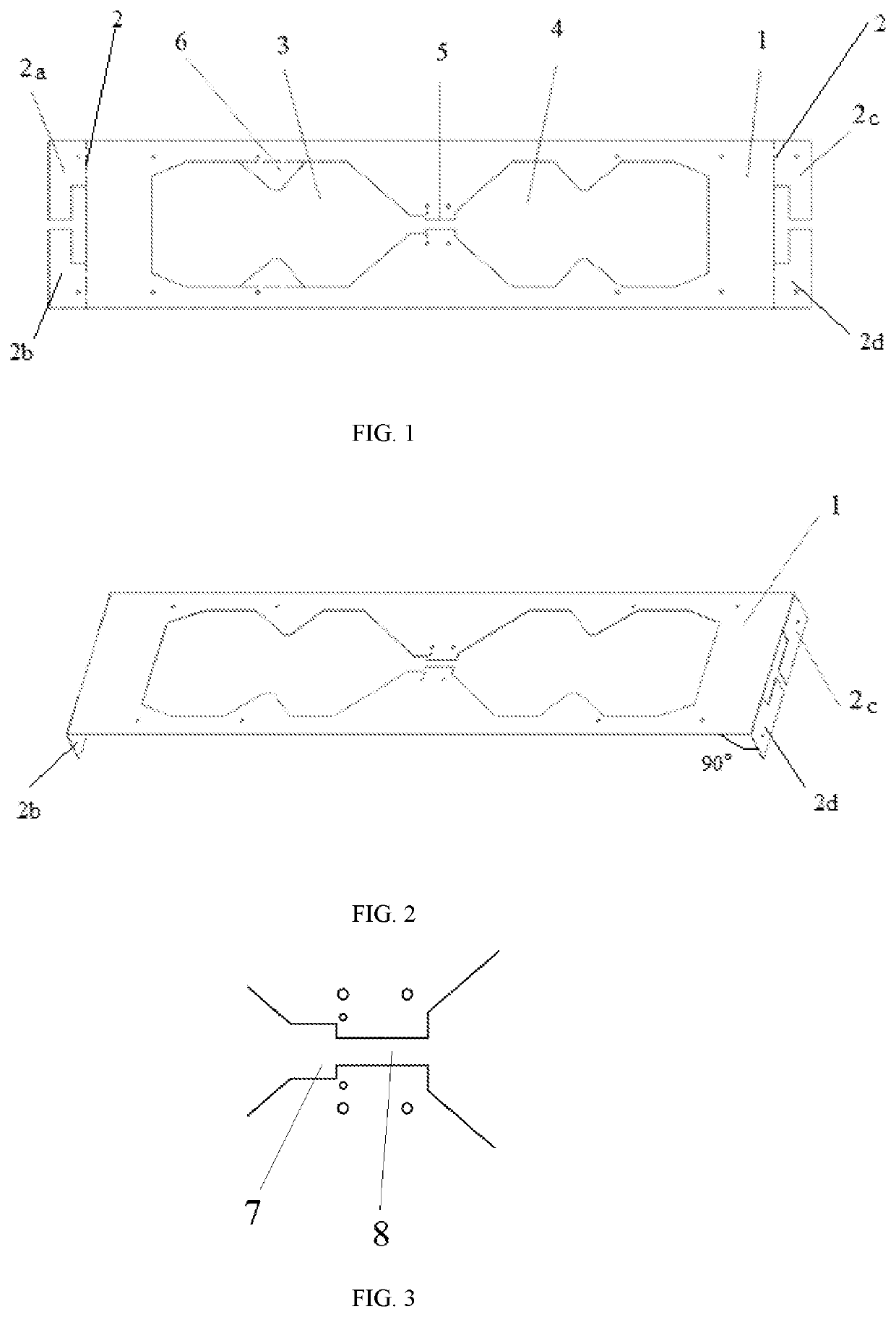
[0021]As shown in FIG. 1, the present embodiment is a planar antenna element including a main radiator 1 and secondary radiators 2. The main radiator 1 is a rectangular metal sheet in which a double gourd-shaped opening is formed. The double gourd-shaped opening includes a first opening 3, a second opening 4 and a feed line part 5. The first opening 3 and the second opening 4 are communicated through the feed line part 5 and are symmetrical to each other. The secondary radiators 5 are arranged on the short sides of the main ra...


PUM


Abstract

The invention relates to a planar antenna element and an antenna. The planar antenna element includes a main radiator and secondary radiators. The main radiator is a rectangular metal sheet in which a double gourd-shaped opening is formed. The double gourd-shaped opening includes a first opening, a second opening and a feed line part. The first opening and the second opening are communicated through the feed line part and are symmetrical to each other. The secondary radiators are arranged on the short sides of the main radiator.

Description

TECHNICAL FIELD[0001]The present invention relates to the technical field of antennas, and specifically relates to a planar antenna element and an antenna.BACKGROUND ART[0002]At present, a planar antenna has element type, slot type and other types, and is commonly characterized by being small in volume, light in weight, small in wind resistance and convenient to install and use. A built-in tuner integrates the antenna with the tuner to facilitate the adjustment. The planar antenna is high in efficiency, and is especially suitable for the reception of live satellite television. With the popularization of wireless digital television signals, more and more people receive television signals outdoors or on the move rather than being limited indoors. Even when watching television indoors, the antennas are needed to be installed at different positions in many environments. At this time, higher requirements are placed on the antennas which are tasked with signal reception: wide receiving fr...

Claims


Application Information

Patent Timeline
Patent Type & Authority Applications(United States)
IPC IPC(8): H01Q9/04H01Q15/14
CPCH01Q9/045H01Q15/14H01Q1/36H01Q9/28H01Q5/371
Inventor YANG, RUIDIAN
Owner SHENZHEN ANTOP TECH
Why Eureka
Try Eureka