Network fabric reconfiguration

Active Publication Date: 2015-10-20
GOOGLE LLC
View PDF22 Cites 54 Cited by
  • Summary
  • Abstract
  • Description
  • Claims
  • Application Information

AI Technical Summary

Benefits of technology

[0002]A according to one aspect of the disclosure, a method for reconfiguring a network includes receiving an indication of a first physical topology of the network that realizes a first logical topology. The physical topology defines the connection of a plurality of nodes in a first layer to a plurality of nodes in a second layer through a plurality of optical circuit switches. The method also includes receiving an indication of a second logical topology to be implemented on the network, and then determining a delta topology. The delta topology includes a set of to-cut links and a set of to-connect links that transforms the first logical topology into the second logical topology. The method includes locating a first decomposable link set in the delta topology within a single optical circuit switch. A decomposable link set includes at least two to-cut links and at least two to-connect links.
[0003]The decomposable link set is selected such that when the at least two to-cut links are cut, the corresponding at least two to-connect links can be connected. For the located first decomposable link set, the to-cut links are cut and the to-connect links are connected. Iteratively, one of the remaining to-cut links is shuffled to a target optical circuit switch yielding a shuffled delta topology. Next, a second decomposable link set is located within the shuffled delta topology, wherein each of the links of the second decomposable link set passes through the target optical circuit switch. The to-cut links are cut and their ends are interconnected.
[0004]According a second aspect of the disclosure, a system for reconfiguring a network includes a plurality of optical circuit switches and a controller coupled to each of the plurality of optical circuit switches. The controller is configured to receive an indication of a first physical topology of a network realizing a first logical topology, wherein the physical topology defines the connection of a plurality of nodes in a first layer to a plurality of nodes in a second layer through the plurality of optical circuit switches. The controller is also configured to receive an indication of a second logical topology to be implemented on the network, and to determine a delta topology comprising a set of to-c

Problems solved by technology

However, when the connections maintained by these switches are broken responsive to the expansion

Method used


Image

  • Network fabric reconfiguration
  • Network fabric reconfiguration
  • Network fabric reconfiguration

Examples


Embodiment Construction

[0022]Following below are more detailed descriptions of various concepts related to, and implementations of, systems and methods for reducing throughput loss during the expansion of a computer network. The various concepts introduced above and discussed in greater detail below may be implemented in any of numerous ways, as the described concepts are not limited to any particular manner of implementation. Examples of specific implementations and applications are provided primarily for illustrative purposes.

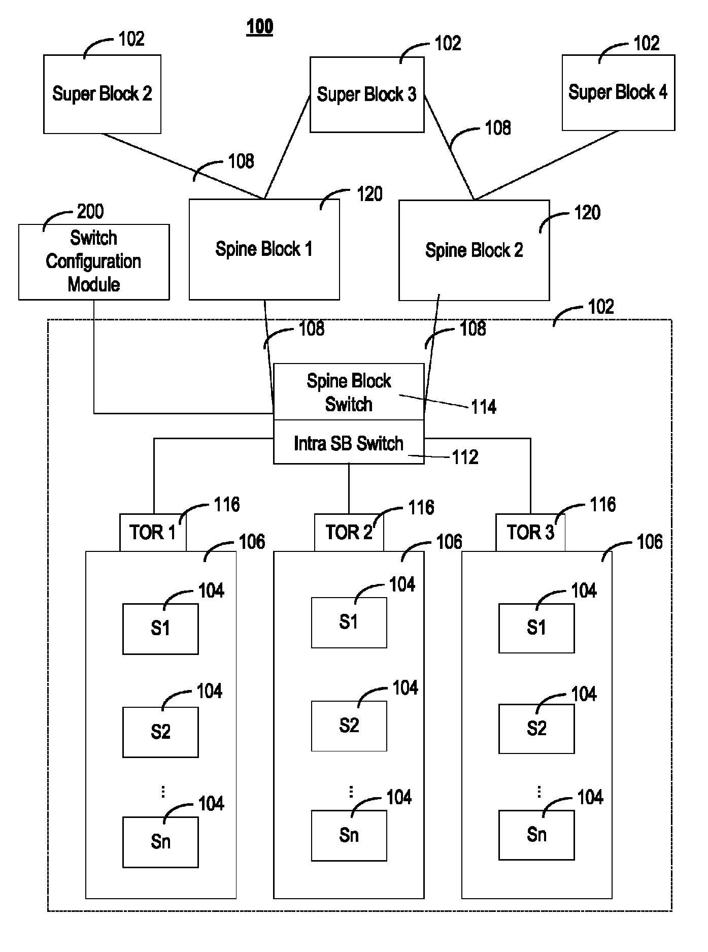
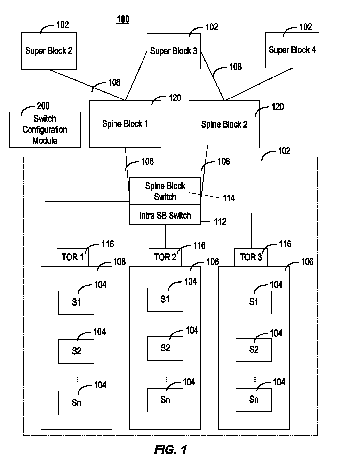
[0023]In some implementations, a datacenter network includes a plurality of optical circuit switches, which provide links between the nodes (or blocks) in the different layers (generally referred to as a first layer and a second layer) of a network. The interconnections between the ports within each optical circuit switch are reprogrammable, enabling the logical connectivity of the datacenter network to be reconfigured without plugging / unplugging cables. In some implementations, du...


PUM


Abstract

The present disclosure describes systems and methods for reconfiguring the links made by a plurality of optical circuit switches between the nodes of the first layer and the nodes of the second layer that reduces the throughput loss when the network transitions form a first logical topology to a second logical topology. More particularly, the first logical topology is realized by a specific physical topology, while the second logical topology may be realized by one or more physical topologies. The disclosure describes a method for selecting a second physical topology from the one or more physical topologies that will realize the second logical topology while reducing the number of links within each of the optical circuit switches that must be reconfigured (i.e, disconnected from their present ports and reconnected to new ports within the optical circuit switch) to transition from the first to second logical topology.

Description

BACKGROUND OF THE DISCLOSURE[0001]Hybrid optical and electrical switches have been suggested to facilitate building modular data centers. However, when the connections maintained by these switches are broken responsive to the expansion of the data center's network, data throughput loss can occur as the connections are reconfigured.SUMMARY[0002]A according to one aspect of the disclosure, a method for reconfiguring a network includes receiving an indication of a first physical topology of the network that realizes a first logical topology. The physical topology defines the connection of a plurality of nodes in a first layer to a plurality of nodes in a second layer through a plurality of optical circuit switches. The method also includes receiving an indication of a second logical topology to be implemented on the network, and then determining a delta topology. The delta topology includes a set of to-cut links and a set of to-connect links that transforms the first logical topology i...

Claims


Application Information

Patent Timeline
IPC IPC(8): H04J14/00H04B10/27H04L12/933H04L12/751H04L12/24H04L12/947H04Q11/00H04L45/02
CPCH04B10/27H04L45/02H04L49/15H04Q11/0071H04L41/12H04L49/25H04Q2011/0052H04Q2011/009H04Q11/0005H04Q2011/005H04Q2011/0054H04Q2011/0086
Inventor FELDERMAN, ROBERTKABBANI, ABDUL
Owner GOOGLE LLC
Why Eureka
Try Eureka