

Exhaust gas recirculation valve
a technology of exhaust gas and valve body, which is applied in the direction of valve operating means/release devices, machines/engines, mechanical equipment, etc., can solve the problem of inability to set gas flow characteristics extremely different, and achieve the effect of accurate flow characteristics and large flow characteristics
- Summary
- Abstract
- Description
- Claims
- Application Information
AI Technical Summary
Benefits of technology
Problems solved by technology
Method used
Image

Examples
first embodiment
[0019]A detailed description of a first embodiment embodying an exhaust gas recirculation valve (EGR valve) according to the present invention will now be given referring to the accompanying drawings.
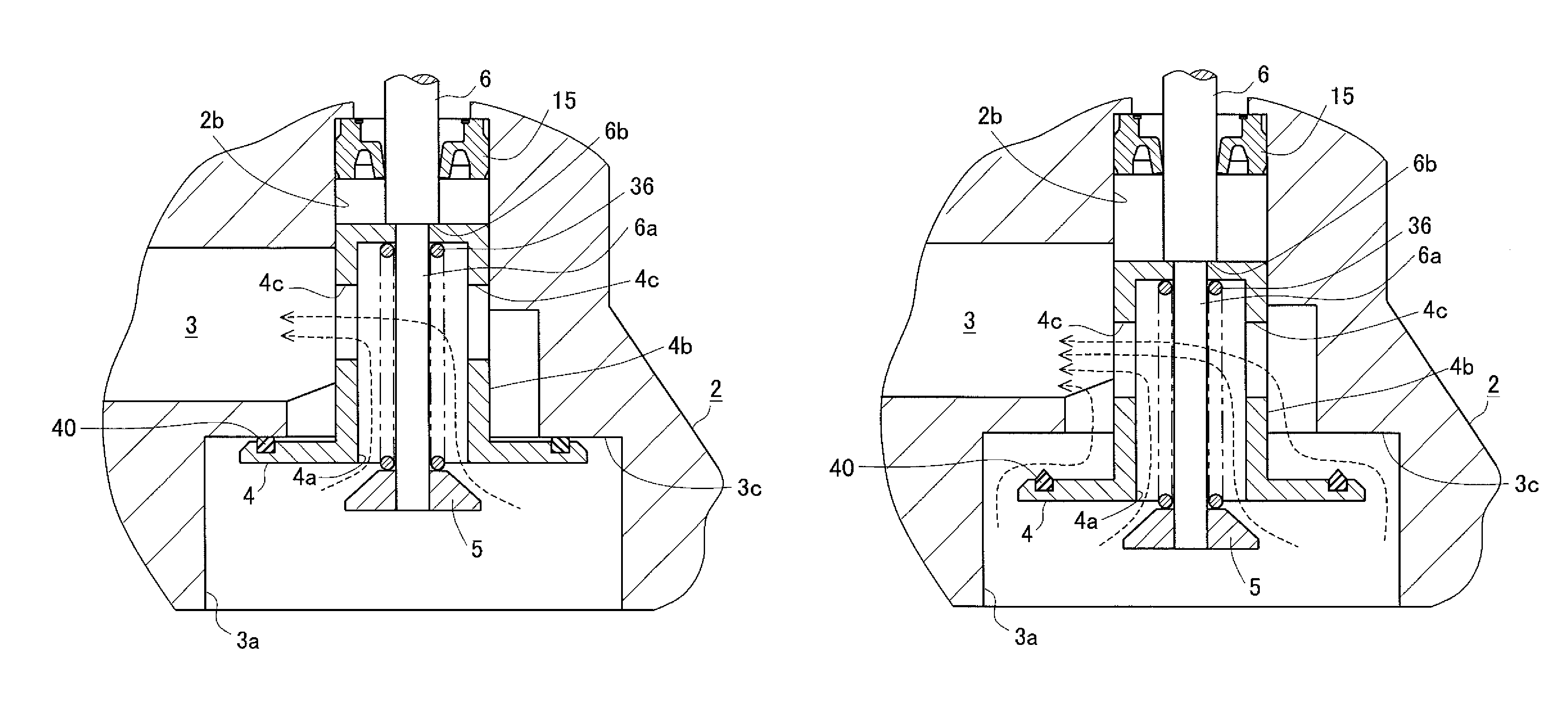
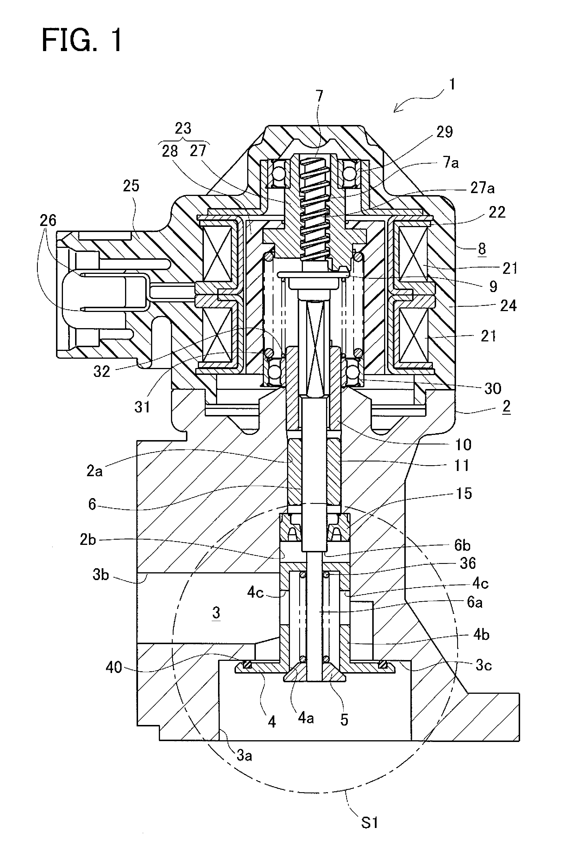
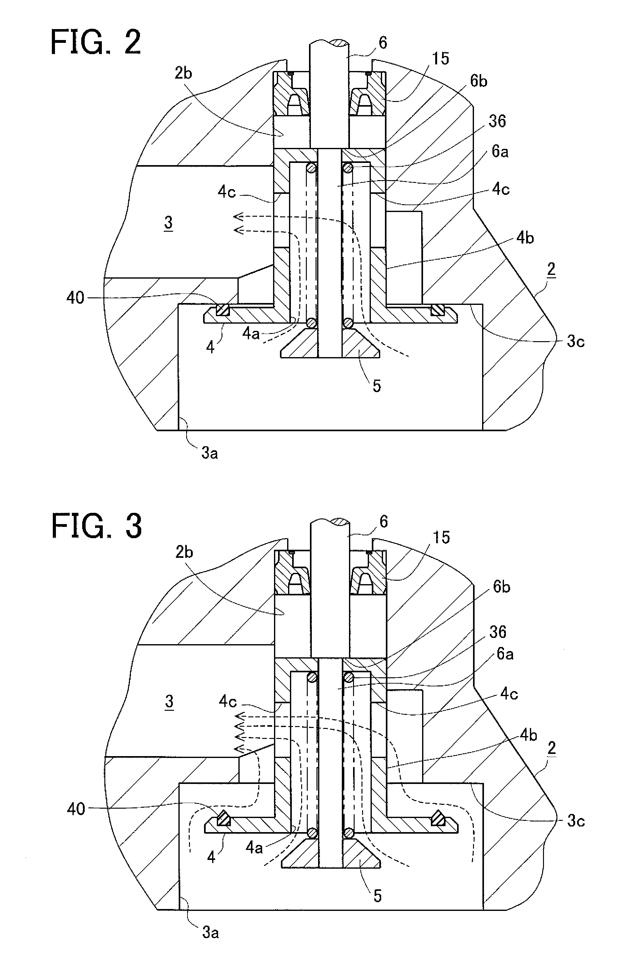
[0020]FIG. 1 is a front cross sectional view showing an EGR valve 1 in a fully closed position. FIG. 2 is an enlarged cross sectional view showing a part S1 circled with a chain line in FIG. 1 in an intermediately open position. FIG. 3 is an enlarged cross sectional view showing the part S1 circled with the chain line in FIG. 1 in a fully open position. The EGR valve 1 is provided in an EGR passage for returning part of exhaust gas (EGR gas) discharged from an engine to the EGR passage to control an EGR gas flow rate. The EGR valve 1 includes a housing 2, a passage 3 for EGR gas formed in the housing 2, a valve seat 4 provided at some place in the passage 3, a valve element 5 provided to be seatable on the valve seat 4, a valve stem 6 integrally provided with the valve element 5 to move...
second embodiment
[0040]an exhaust gas recirculation valve (an EGR valve) according to the invention will be explained below in detail referring to the accompanying drawings.
[0041]In this embodiment, similar or identical parts to those in the first embodiment are given the same reference signs as those in the first embodiment and their details are not repeatedly explained. The following explanation is thus made with a focus on differences from the first embodiment.
[0042]FIG. 5 is a front sectional view of the EGR valve 1 in a fully closed position. FIG. 6 is an enlarged cross sectional view showing a part S1 circled with a chain line in FIG. 5 in an intermediately open position. FIG. 7 is an enlarged cross sectional view showing the part S1 circled with the chain line in FIG. 5 in a fully open position. The present embodiment differs from the first embodiment in the configurations of a valve seat 4, a valve element 5, an engagement part, and others.
[0043]The present embodiment does not include the cy...
PUM
 Abstract
Description
Claims
Application Information