Point load sensor

a load sensor and point technology, applied in the field of load sensors, can solve the problems of damage to the array, difficult measurement of the force applied by the handling system to the material, and inability to measure,

Inactive Publication Date: 2015-11-03
UNITED STATES OF AMERICA
View PDF3 Cites 2 Cited by
  • Summary
  • Abstract
  • Description
  • Claims
  • Application Information

AI Technical Summary

Benefits of technology

[0013]It is a still further object of the present invention to provide a system and method of use for reducing sensor orientation errors.
[0015]The two strain measurements are corrected and combined to recover the compressive force on the ring. The sensor employs a method for calibrating and resolving the compressive force that does not require the angle of loading or sensor orientation as an input; thereby, allowing resolution irrespective of the direction of the compression. Accordingly, the method results in the reduction of sensor orientation errors.
[0020]The relationship for UP can be generalized to UP=A(V1+V2)+√{right arrow over (B(V1+V2)2−C(V12+V22))}{right arrow over (B(V1+V2)2−C(V12+V22))}. The coefficients A, B and C can be initialized assuming their corresponding values based on the assumption of a thin ring and iteratively varied along with the slopes and offsets; thereby, allowing generalization to rings that may not be thin.
[0030]Calibrating the sensor ring for load orientation can further include minimizing a standard deviation of an uncorrected load, UP, wherein:UP=A(V1+V2)+√{right arrow over (B(V1+V2)2−C(V12+V22))}{right arrow over (B(V1+V2)2−C(V12+V22))};  [2]

Problems solved by technology

During the handling of cabling, piping, or other tubular materials, forces are applied to the material by the handling system that can be difficult to measure.
Any problems with the towed array handling system may result in the application of unacceptable forces to the array that can damage the array.
However, the design of this sensor does not take into consideration the variation of strain inside a ring under diametric compression.
Without this consideration, the placement and wiring of the strain gauges, as well as the means of combining the outputs, can result in orientation errors greater than thirty percent.

Method used


Image

  • Point load sensor
  • Point load sensor
  • Point load sensor

Examples


Embodiment Construction

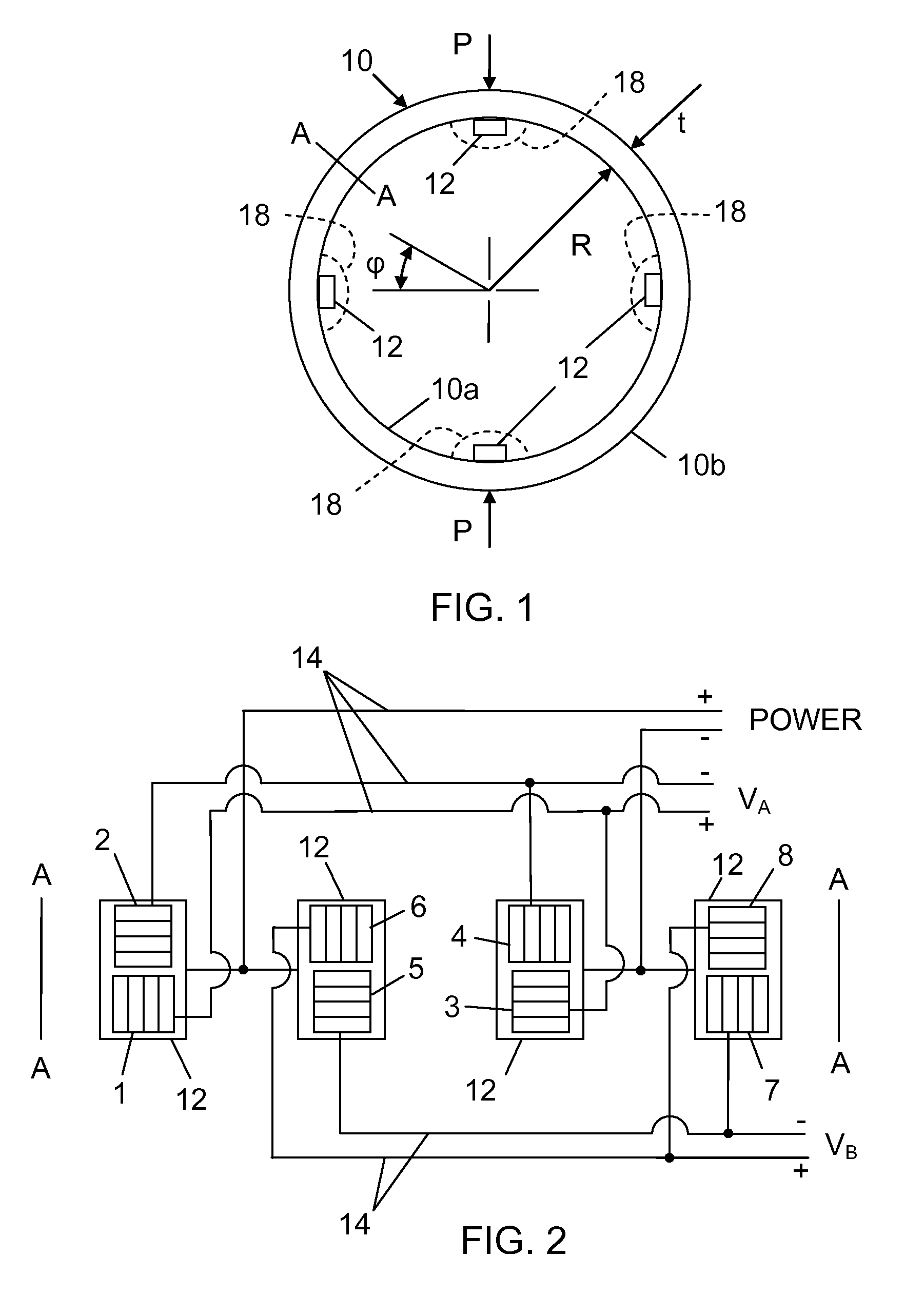
[0043]Referring to FIG. 1, there is shown a sensor ring 10, with an inner radius R and a thickness t. Diametrically opposed forces P are applied to the sensor ring 10, such that the sensor ring is placed in diametric compression. As is known in the art, there will be a bending moment through the thickness, t, of the sensor ring 10 at all points from this type of loading.

[0044]Considering a bending moment M at some angle φ, it is known in the art that the following relationship holds for a thin ring:

[0045]M=P·R2⁢(cos⁡(φ)-2π),-π2≤φ≤π2.[3]

It has also been shown in the art that the use of Equation [3] for thick rings is often sufficient. For thick rings having section thickness to radius ratios (t / R) as great as ½, the error introduced by the use of Equation [3] is approximately four percent.

[0046]From Equation [3], it can be surmised that the strain inside of the sensor ring 10 will be:

[0047]ɛ=P·R·t4·E·I⁢(cos⁡(φ)-2π),[4]

where:

[0048]ε=strain;

[0049]E=Young's modulus for the ring material...


PUM

PropertyMeasurementUnit
diametric compressive forceaaaaaaaaaa
thicknessaaaaaaaaaa
output voltagesaaaaaaaaaa

Abstract

A point load sensor measures compressive forces exerted on the outside of a ring in diametric compression irrespective of the direction of application of the force. The sensor consists of a ring with strain gauges placed in a configuration to measure the circumferential strain at two positions on the ring ninety degrees apart resulting from bending of the ring as the ring is loaded in diametric compression. The two measurements are corrected and combined to recover the compressive force on the ring. A method for calibrating and resolving the compressive force does not require the angle of loading or sensor orientation as an input, thus allowing resolution irrespective of the direction of the compressive force.

Description

STATEMENT OF GOVERNMENT INTEREST[0001]The invention described herein may be manufactured and used by or for the Government of the United States of America for governmental purposes without the payment of any royalties thereon or therefore.CROSS REFERENCE TO OTHER PATENT APPLICATIONS[0002]Not applicable.BACKGROUND OF THE INVENTION[0003](1) Field of the Invention[0004]The present invention relates to load sensors and more particularly to a sensor for measuring forces exerted on a ring in diametric compression.[0005](2) Description of the Prior Art[0006]During the handling of cabling, piping, or other tubular materials, forces are applied to the material by the handling system that can be difficult to measure. As an example, thin line sonar arrays that are towed behind submarines.[0007]As the arrays are deployed from and retrieved, the array passes through various parts of the handling system. Any problems with the towed array handling system may result in the application of unacceptab...

Claims


Application Information

Patent Timeline
Patent Type & Authority Patents(United States)
IPC IPC(8): G01L1/00G01L1/22
CPCG01L1/22G01L25/00
Inventor SEFRANEK, JEFFREY K.
Owner UNITED STATES OF AMERICA
Why Eureka
Try Eureka