Method for detecting falls and a fall detector

a technology of fall detection and detection method, which is applied in the direction of instruments, diagnostic recording/measuring, diagnostics, etc., can solve the problems of significant injuries, inability to push the button, and inability to receive help for a significant period of tim

Active Publication Date: 2015-11-03
KONINK PHILIPS ELECTRONICS NV
View PDF6 Cites 31 Cited by
  • Summary
  • Abstract
  • Description
  • Claims
  • Application Information

AI Technical Summary

Problems solved by technology

Falls affect millions of people each year and result in significant injuries, particularly among the elderly.
However, if the user suffers a severe fall (for example if they are knocked unconscious), the user might be unable to push the button, which might mean that help doesn't arrive for a significant period of time, particularly if the user lives alone.
However, it has been found that these fall detectors have an unfavourable trade-off between fall detection probability and false alarm rate.
Given that a high false alarm rate will result in additional costs to the organisation responsible for giving assistance to the user of the fall detector (i.e. they will need to contact or visit the user of the fall detector when the fall detection alarm is triggered) and that a high false alarm rate is undesirable for the user of the fall detector, it has been found that an economically viable fall detector should provide a false alarm rate of, say, less than one false alarm in each two-month period, while maintaining a (positive) fall detection probability above 95 percent.
However, these existing fall detectors do not meet the detection requirements set out above.
Thus, one of the main disadvantages of existing fall detectors is their moderate reliability as expressed by a Receiver Operating Curve (ROC).
Even with an extended set of features (i.e. determining more than just an impact from the accelerometer measurements and a change in height from the pressure sensor measurements), it has been found that it is difficult to obtain a satisfactory performance if each feature is simply compared to a threshold and the subsequent reasoning only involves the feature-wise binary outcomes of these comparisons.

Method used


Image

  • Method for detecting falls and a fall detector
  • Method for detecting falls and a fall detector
  • Method for detecting falls and a fall detector

Examples


Embodiment Construction

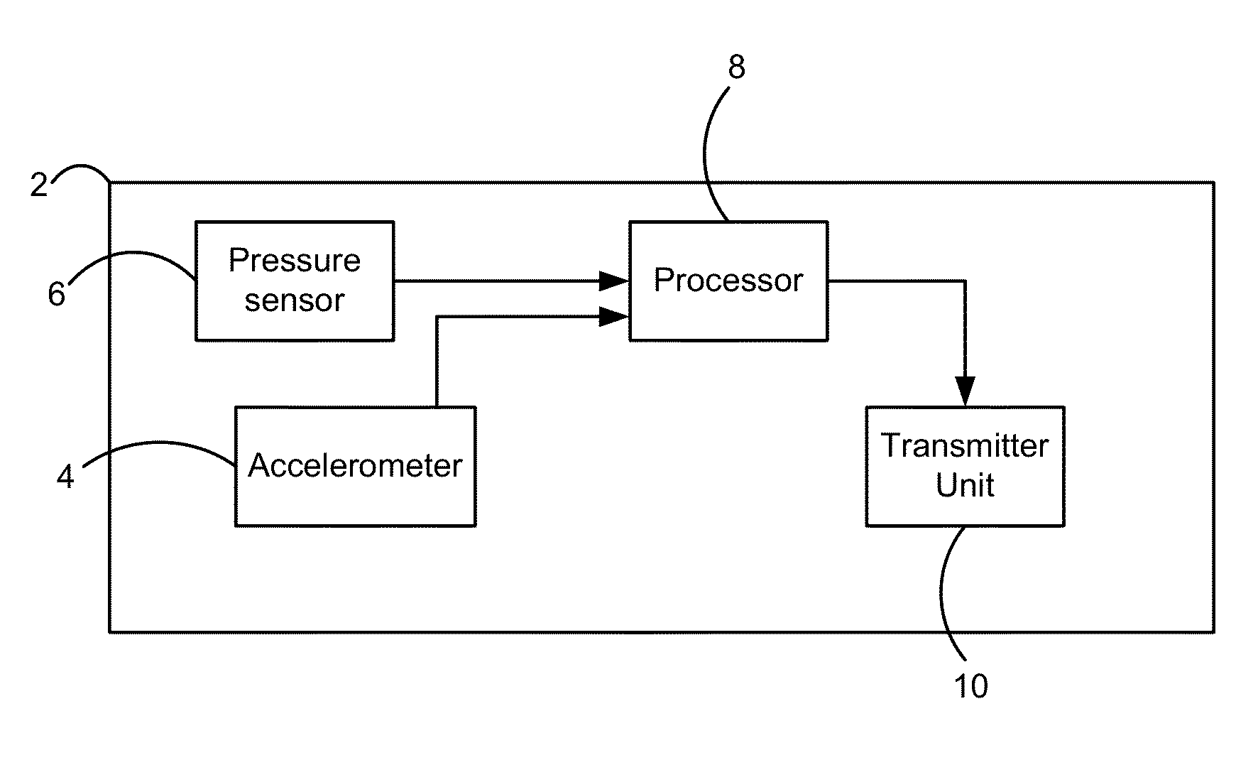
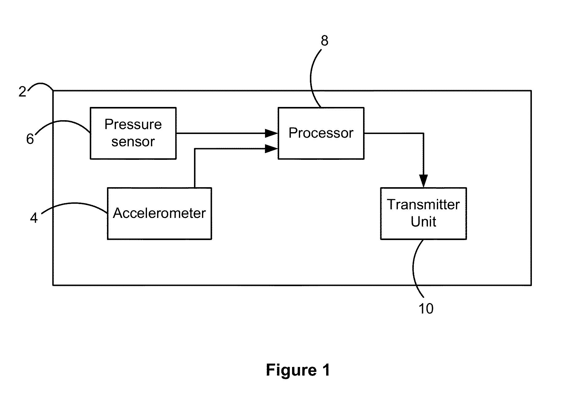
[0024]A fall detector 2 according to an embodiment of the invention is shown in FIG. 1. The fall detector 2 is designed to be worn by a user, for example on their wrist, at their waist or on their chest or back, without adversely affecting the movement or balance of the user. In a preferred embodiment, such as that shown in FIG. 1, the fall detector 2 can be designed as a pendant to be worn around the neck of the user.

[0025]In this exemplary embodiment, the fall detector 2 comprises two sensors, an accelerometer 4 and pressure sensor 6, which are connected to a processor 8. The processor 8 receives measurements from the sensors 4, 6, and processes the measurements to determine if a user of the fall detector 2 has suffered a fall.

[0026]The fall detector 2 also comprises a transmitter unit 10 that allows the fall detector 2 to transmit an alarm signal to a base station associated with the fall detector 2 (which can then issue an alarm or summon help from a healthcare provider or the e...


PUM


Abstract

A method for detecting a fall by a user includes a method of detecting a fall by a user. The method includes processing measurements obtained from one or more sensors to extract a respective value for a plurality of features associated with a fall. A respective log likelihood ratio for each of the values is determined. Whether the user has fallen is determined based on the determined log likelihood ratios.

Description

CROSS-REFERENCE TO RELATED APPLICATIONS[0001]This application is a Continuation-in-Part application under 35 USC §120 of U.S. application Ser. No. 13 / 510,408, filed May 17, 2012, the contents of which is incorporated herein by reference.TECHNICAL FIELD OF THE INVENTION[0002]The invention relates to a method for detecting falls by a user and a fall detector, and in particular the invention relates to a method and a fall detector that has an improved fall detection rate and a reduced false alarm rate.BACKGROUND TO THE INVENTION[0003]Falls affect millions of people each year and result in significant injuries, particularly among the elderly. In fact, it has been estimated that falls are one of the top three causes of death in elderly people. A fall can be defined as a sudden, uncontrolled and unintentional downward displacement of the body to the ground followed by an impact.[0004]Personal Help Buttons (PHBs) are available that require the user to push the button to summon help in an e...

Claims


Application Information

Patent Timeline
Patent Type & Authority Patents(United States)
IPC IPC(8): G01P15/00G01C5/06G06F17/18A61B5/11A61B5/00
CPCG06F17/18A61B5/1117A61B5/7246G01C5/06G01P15/00G08B21/043G08B21/0446G08B25/016
Inventor BAGGEN, CONSTANT PAUL MARIE JOZEFCHEN, NINGJIANG
Owner KONINK PHILIPS ELECTRONICS NV
Why Eureka
Try Eureka