Pressure detection system for a pressure cooker indicating use-related wear

a technology of pressure detection system and pressure cooker, which is applied in the field of pressure detection system for pressure cooker, can solve the problems of rising pressure in the pressure cooker, affecting changing the properties of the safety device, so as to improve the operability of the pressure detection device, the effect of restoring the tappet force and simple techniqu

Active Publication Date: 2015-11-03
FISSLER
View PDF7 Cites 65 Cited by
  • Summary
  • Abstract
  • Description
  • Claims
  • Application Information

AI Technical Summary

Benefits of technology

[0010]In order to avoid miscounts as a result of external influences of the measured value of the sensor, for example when cleaning the pressure cooker, the computer unit can be designed in accordance with a preferred development of the invention to check whether the measured value has reached the first threshold value in an uninterrupted manner for a specific (first) period of time, and to continue the counter only once the first threshold value has been reached without interruption for the first period of time. This period of time can be a few seconds or minutes for example; the period of time is preferably between 10 seconds and 1 minute, for example 15 or 25 seconds. The reliability of the wear display integrated into the pressure detection system is thus increased significantly.
[0038]In accordance with a further aspect of the pressure detection system according to the invention, a communication module in particular connected to the computer unit for wireless communication with a stove or a heating output regulation or control unit of a stove can be provided in the pressure detection system. The computer unit is then preferably designed, in the event that a threshold value is reached, to send a communication to the stove or the heating output regulation or control unit. The heating output can thus be adjusted or set automatically so that the desired pressure is maintained in the pressure cooker during the cooking process. This leads on the one hand to energy-optimized heating and on the other hand constitutes a safety function, since, if the threshold value for an excessively high pressure is exceeded, the heating output can be reduced immediately. Since an overheating of the pressure cooker also leads to increased wear, the wear is thus also reduced and a reliable wear display is benefitted. This signal can then also be used when controlling or regulating automatic cooking processes in order to achieve a better cooking result by means of an optimal setting of the cooking pressure.

Problems solved by technology

This results in a rise in pressure in the pressure cooker.
A problem of pressure cookers of this type lies in the fact that they contain five safety-relevant closure parts.
Both materials have the disadvantage that the properties thereof change as a result of use and / or age.
For example, this may result in the fact that, when the ring seal is worn as a result of frequent use or excessive age, safety devices are no longer responsive at a high pressure level or are only responsive at a high pressure level.
They may then no longer reliably perform the pressure relief function in some circumstances when an excessive pressure is produced in the pressure cooker.
In the worst-case scenario, this may cause the lid to be lifted off at high pressure and could be life-threatening.
It has been found that the wearing parts of pressure cookers are used too long and are replaced too late in practice.
This is also down to the fact that the consumer generally loses track of when he purchased a pressure cooker and for example of when the ring seal was last replaced.

Method used


Image

  • Pressure detection system for a pressure cooker indicating use-related wear
  • Pressure detection system for a pressure cooker indicating use-related wear
  • Pressure detection system for a pressure cooker indicating use-related wear

Examples


Embodiment Construction

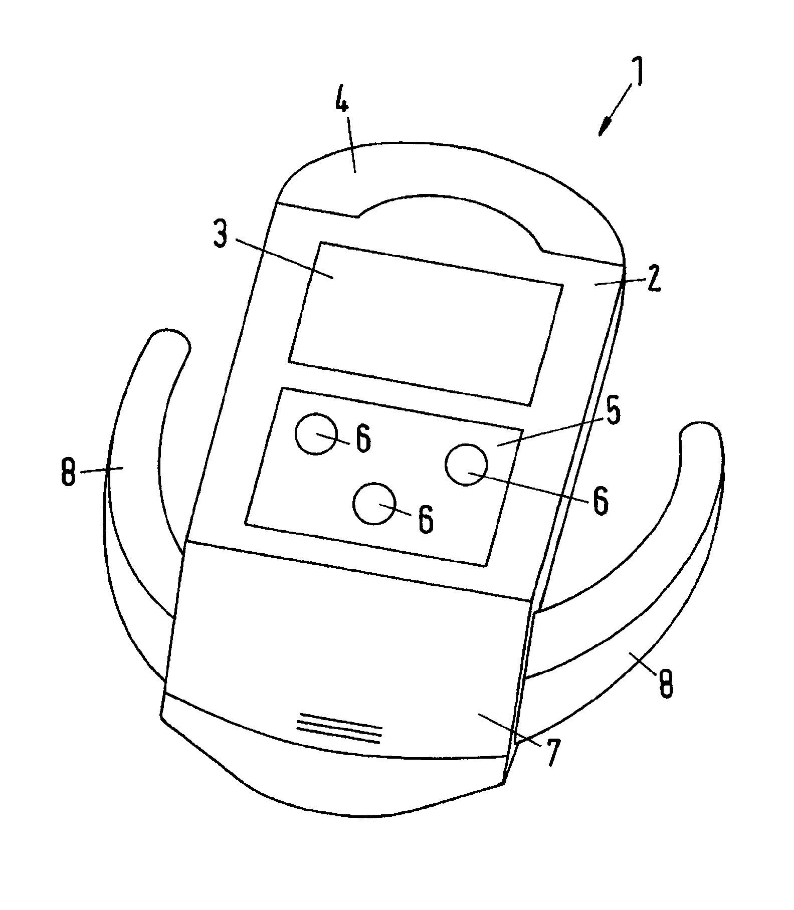
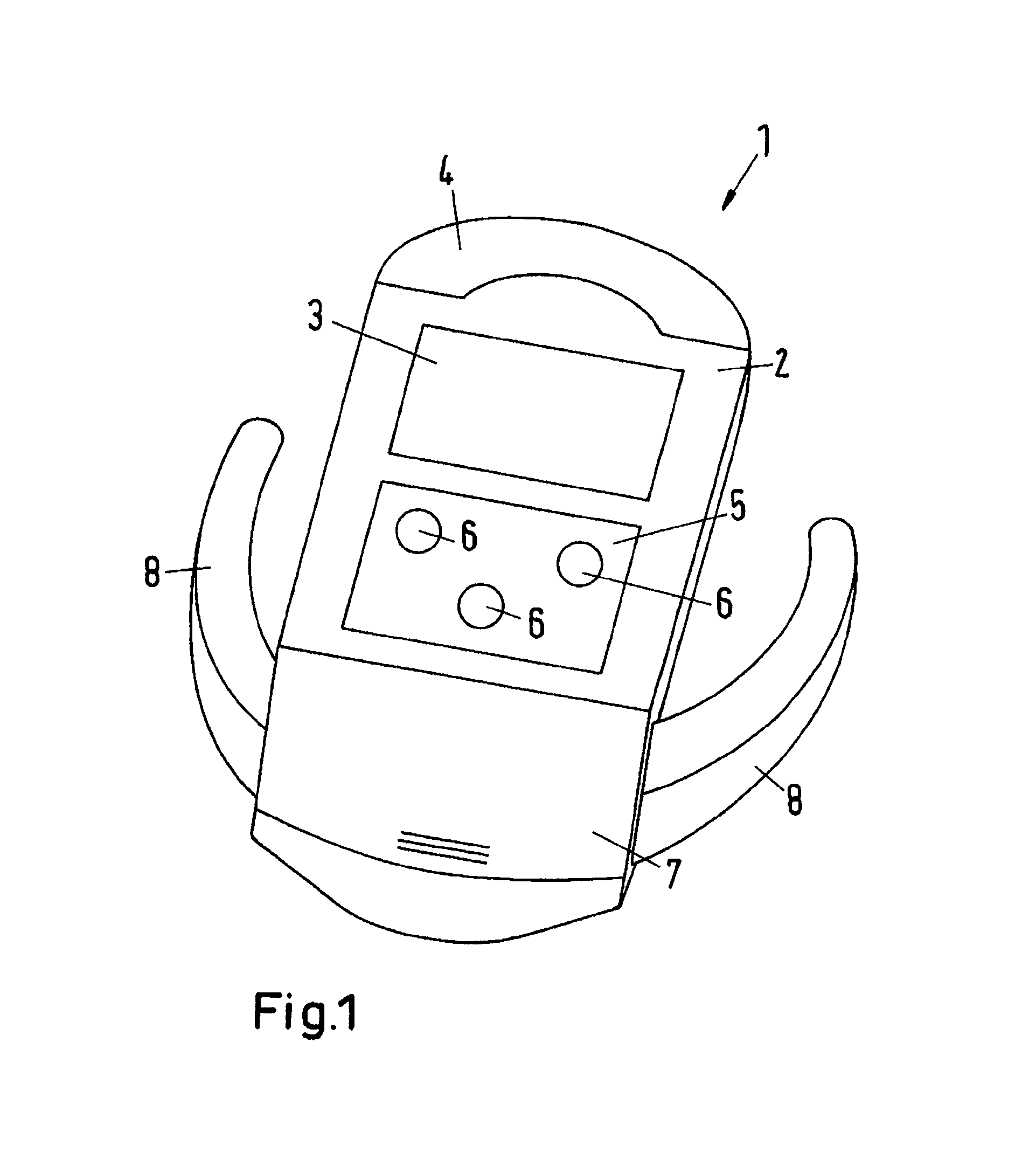
[0045]In FIG. 1, the pressure detection device 2 of the pressure detection system 1 according to the invention is illustrated, in which a key aspect of the present invention is implemented by a wear display for wearing parts of a pressure cooker. The pressure detection system 1 formed merely by this pressure detection device 2 therefore also forms the present invention.

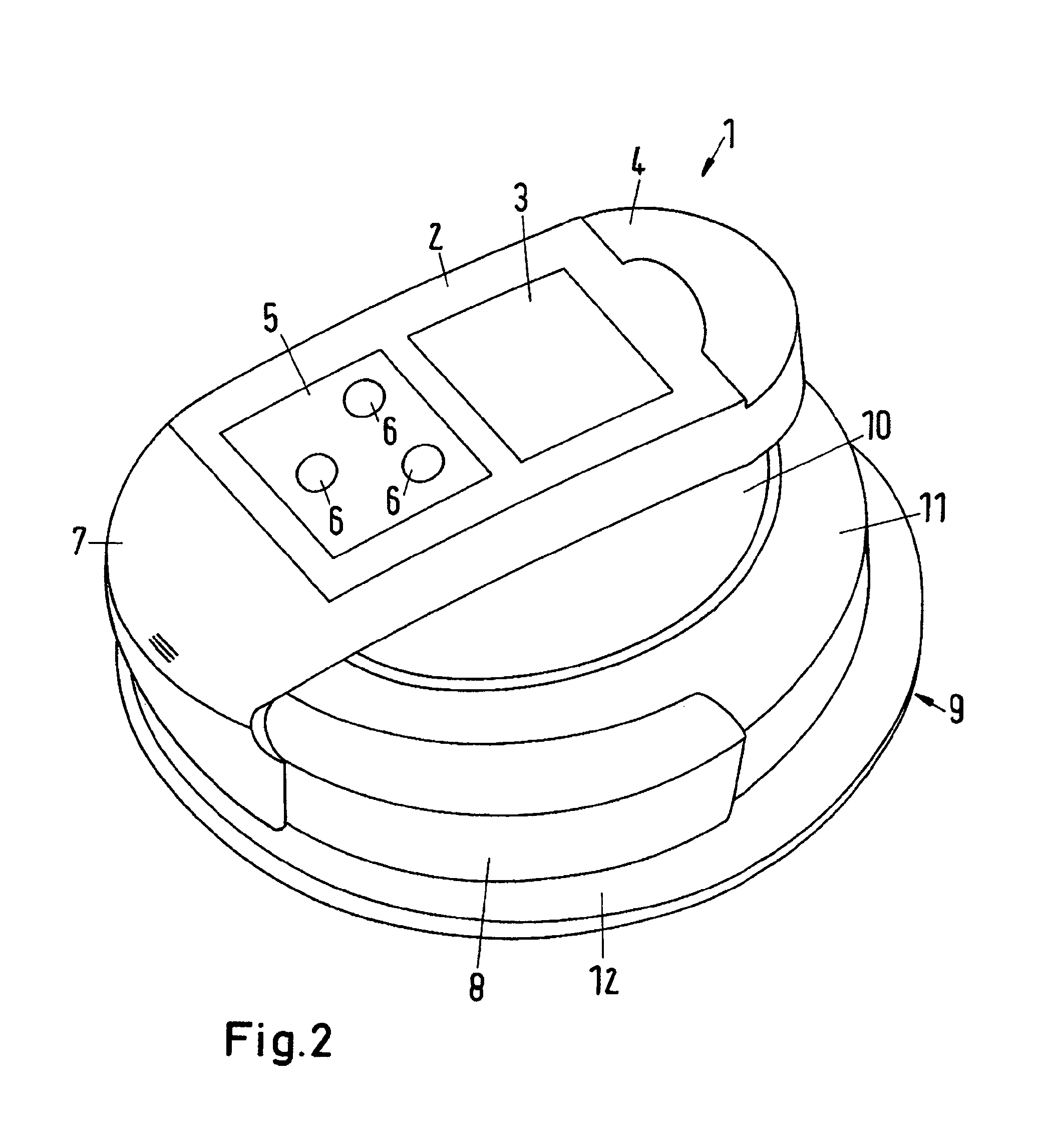
[0046]The pressure detection device 2 comprises a first display 3, which is formed as an LC display (LCD) and on which various pieces of information can be illustrated in the form of text or by symbols. Furthermore, a second display 4 is provided, which is formed by a plurality of differently colored light-emitting diodes (LEDs) beneath a transparent cover. Furthermore, the pressure detection device 2 comprises an operating interface 5 with operating buttons 6, by means of which the user can make inputs into the pressure detection device 2, which can preferably be made in cooperation with the first and / or second optic...


PUM

PropertyMeasurementUnit
timeaaaaaaaaaa
timeaaaaaaaaaa
timeaaaaaaaaaa

Abstract

The invention describes a pressure detection system for a pressure cooker, having a sensor (17) for detecting a pressure prevailing inside the pressure cooker by means of measured values, a computer unit (16) connected to the sensor (17), and a display (3, 4), wherein the computer unit (16) is designed to evaluate the measured values supplied by the sensor (17) and to establish whether at least one first threshold value (S1) has been reached. In order to indicate use-related wear, the computer unit (16) is further designed to continue a counter when the measured value reaches the first threshold value (S1) and to output a notification on the display (3, 4) when a predefined value of the counter is reached.

Description

TECHNICAL FIELD[0001]The invention relates to a pressure detection system for a pressure cooker, comprising a sensor for detecting a pressure prevailing inside the pressure cooker by means of measured values, a computer unit connected to the sensor, and a display, the computer unit being designed to evaluate the measured values supplied by the sensor and to establish whether at least one first threshold value has been reached, for example whether said at least one first threshold value has been overshot or undershot. Here, in accordance with the invention, the pressure does not have to be detected in conventional pressure measurement units. In the present application, the detection of a pressure prevailing inside the pressure cooker means that sensor measured values are detected in any units that depend in a defined manner on the pressure inside the pressure cooker and are therefore a measure for the pressure prevailing in the pressure cooker without having to specify the pressure e...

Claims


Application Information

Patent Timeline
Patent Type & Authority Patents(United States)
IPC IPC(8): G08B21/00G01L19/08A47J27/09G08B21/18A47J27/08A47J27/62
CPCG08B21/182A47J27/0802A47J27/09A47J27/62G01L19/083A47J36/321A47J27/08G01L11/00
Inventor FISSLER, FOLKHART
Owner FISSLER
Why Eureka
Try Eureka