Milking system and method for milking a herd of dairy animals

a dairy animal and milking system technology, applied in the field of milking systems for dairy animals, can solve the problems reduced milk production capacity of this milking device, and reduced health of slow dairy animals, so as to reduce waiting time for the second group of dairy animals and limit the rotational speed of each carrousel

Active Publication Date: 2015-11-10
LELY PATENT
View PDF13 Cites 5 Cited by
  • Summary
  • Abstract
  • Description
  • Claims
  • Application Information

AI Technical Summary

Benefits of technology

[0009]A further advantage of the invention is that the waiting time for the second group of dairy animals is reduced, which is beneficial for the health of the dairy animals of the second group of dairy animals.
[0010]It is possible that the milking system is configured to admit one or more dairy animals classified in the first group to only the first milking device in order to milk said dairy animals by the first milking device, and that the milking system is configured to admit one or more dairy animals classified in the second group to only the second milking device in order to milk said dairy animals by the second milking device. The first and second milking devices each comprise milking stalls which are each provided with milking facilities for milking a dairy animal. During operation, the dairy animals classified in the first group are led to the first milking device, while the dairy animals classified in the second group are led to the second milking device. During maintenance or repair of one of the milking devices it is incidentally possible that the dairy animals intended for the milking device in question are admitted to the other, still operating milking device.
[0011]The estimated treatment time for the milking of a dairy animal can be determined on the basis of different parameters. The estimated treatment time for the milking of a dairy animal comprises, for example, an estimated milking time for milking said dairy animal and / or an estimated pre-treatment time for pre-treating said dairy animal prior to the milking and / or an estimated post-treatment time for post-treating said dairy animal after the milking. The pre-treatment time depends, for example, on a time for pre-cleaning the teats of said dairy animal and / or an estimated connection time for connecting the teat cups to the teats of said dairy animal. The estimated treatment time can be calculated on the basis of the above-mentioned parameters and / or other parameters or be determined in another manner by the control device which is provided with a memory with historical data of the dairy animals of the herd.
[0012]It is possible for the control device to be designed to classify each dairy animal to be milked that has been identified by the identification device in the first group of dairy animals if the estimated treatment time for the milking of said dairy animal is shorter than a threshold value and to classify each dairy animal to be milked that has been identified by the identification device in the second group of dairy animals if the estimated treatment time for the milking of said dairy animal is longer than that threshold value. The threshold value determines the number of dairy animals which are classified in the first and the second group of dairy animals per unit of time. For, in dependence on the threshold value, more or fewer dairy animals are allotted to the first and the second group of dairy animals. The threshold value can be adjustable and variable over time.
[0013]In one embodiment, the first milking device comprises a first carrousel and the second milking device comprises a second carrousel, wherein each carrousel is provided with a plurality of milking stalls for in each case one dairy animal. In this case, it is possible that the rotational speed of the first carrousel is adjustable on the basis of the longest estimated treatment time for the milking of the dairy animals admitted to the first carrousel, wherein the rotational speed of the second carrousel is adjustable on the basis of the longest estimated treatment time for the milking of the dairy animals admitted to the second carrousel. The rotational speed of each carrousel is limited by the dairy animal with the longest estimated treatment time present on that carrousel. As, during operation, dairy animals are continuously admitted to the carrousels and continuously leave the carrousels, the longest estimated treatment time for the milking of the dairy animals admitted to the carrousels will vary over time for each carrousel. The velocities of the carrousels can be adjusted over time to the varying longest estimated treatment time. Incidentally, the longest estimated treatment time defines an upper limit for the rotational speed of the carrousels. It is possible that the rotational speeds of the carrousels are lower than the maximum rotational speed which is defined by the longest estimated treatment time. This can, for example, be favourable for optimizing the milking system as a whole.
[0014]It is possible that the rotational speed of the first carrousel, the rotational speed of the second carrousel and the threshold value are adjustable by the control device, and that the rotational speed of the first carrousel, the rotational speed of the second carrousel and the threshold value are set in such a manner that the number of dairy animals which are classified by the control device in the first group per unit of time substantially equals the number of dairy animals milked which leave the first carrousel per unit of time, and the number of dairy animals which are classified by the control device in the second group per unit of time substantially equals the number of dairy animals milked which leave the second carrousel per unit of time.

Problems solved by technology

However, the milk production capacity of this milking device is still limited.
Moreover, the health of the slow dairy animals is adversely affected by their delay in the waiting area.
Waiting makes these dairy animals restless.
Furthermore, the tension in the udders of these dairy animals during the waiting time can result in medical conditions.

Method used


Image

  • Milking system and method for milking a herd of dairy animals
  • Milking system and method for milking a herd of dairy animals
  • Milking system and method for milking a herd of dairy animals

Examples


Embodiment Construction

[0032]The following is a description of certain embodiments of the invention, given by way of example only and with reference to the drawings.

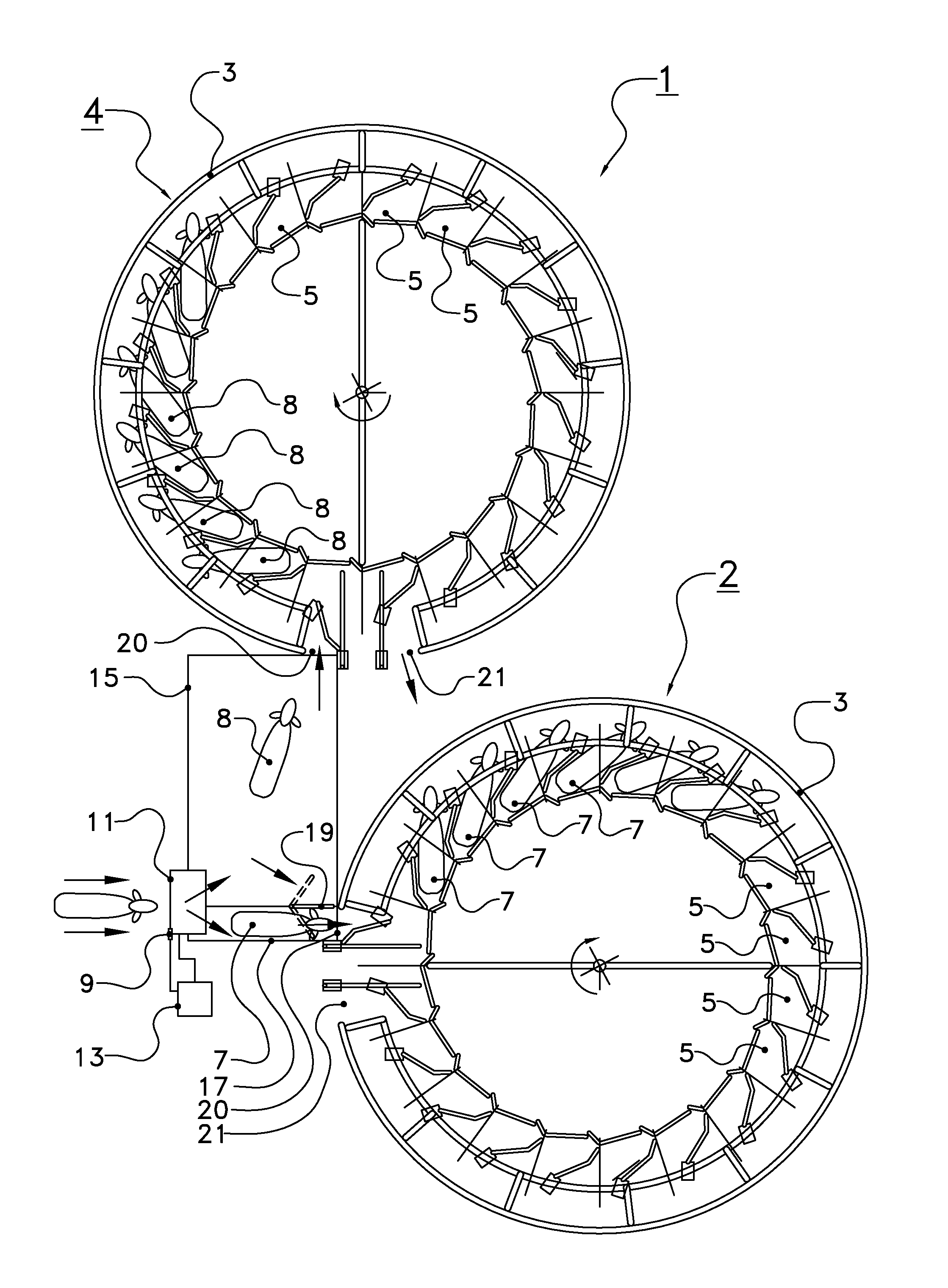
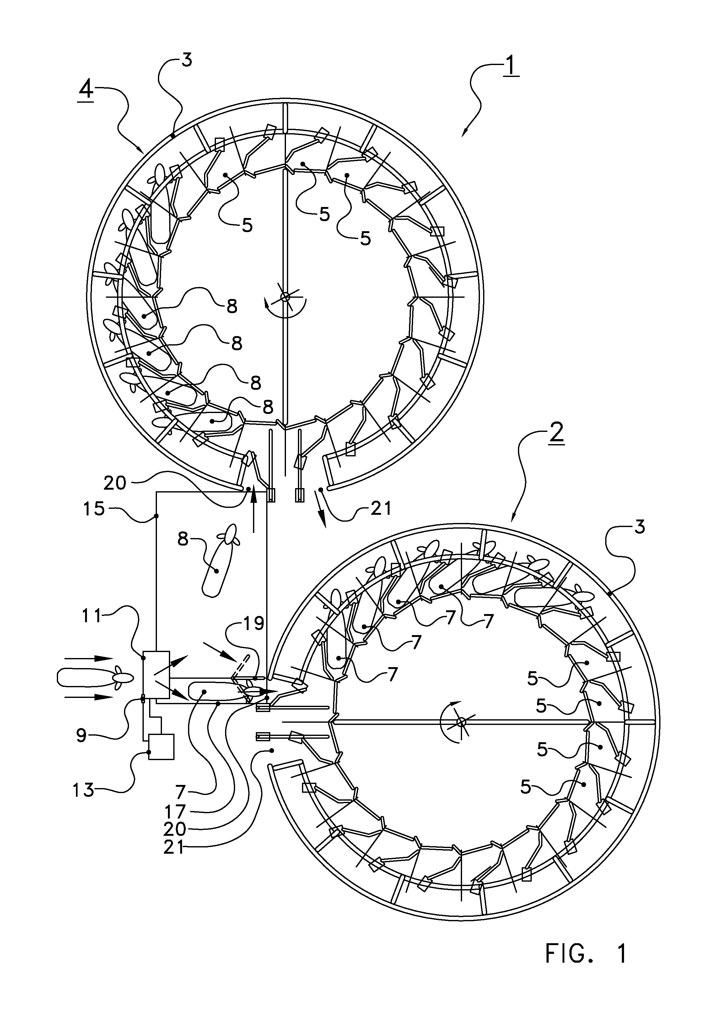
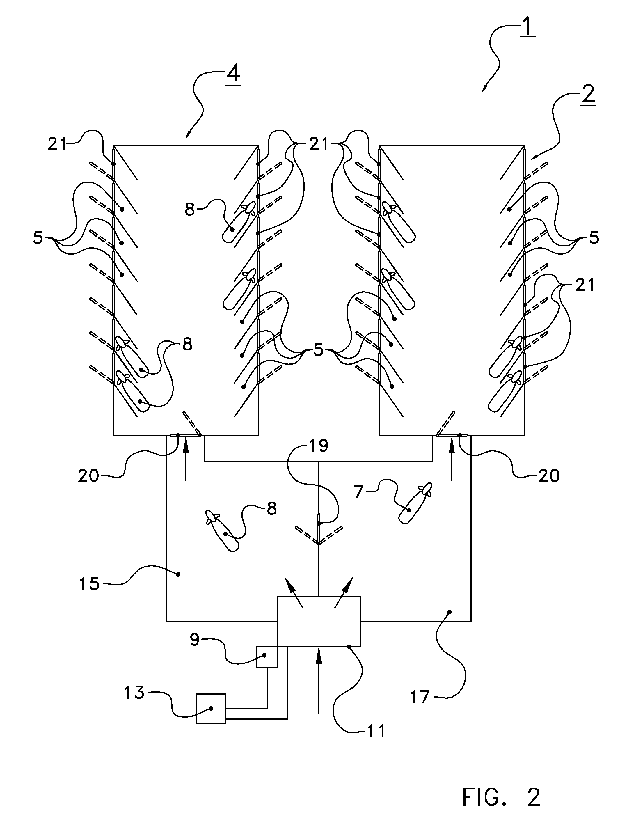
[0033]The milking system for milking a herd of dairy animals is indicated as a whole by 1 in FIG. 1. The milking system 1 comprises two milking devices 2, 4 which are designed as carrousels in this exemplary embodiment. Each carrousel 2, 4 comprises a round rotating platform 3 which is rotatable about a substantially vertical centre line (see the arrows). The carrousels 2, 4 are each drivable by a drive device (not shown). On the rotating platform 3 of each carrousel 2 there are provided a number of milking stalls 5 which are each provided with milking facilities. Each carrousel 2, 4 has an entrance 20 for admitting a dairy animal to the carrousel 2, 4. From the entrance 20 the admitted dairy animal is led into one of the milking stalls 5. Each of the carrousels 2, 4 is also provided with an exit 21. After an almost complete rotation, the dair...


PUM


Abstract

A milking system for milking a herd of dairy animals includes a first milking device and a second milking device, an identification device for identifying dairy animals to be milked of a herd of dairy animals, and a control device for determining an estimated treatment time of each dairy animal to be milked. The control device also classifies each dairy animal to be milked with the aid of a criterion on the basis of the estimated treatment time in at least a first or second group of dairy animals. The milking system admits the first group of dairy animals to preferably only the first milking device and admits the second group to preferably only the second milking device.

Description

CROSS REFERENCE TO RELATED APPLICATIONS[0001]This application is a continuation of PCT application number PCT / NL2010 / 000162 filed on 9 Nov. 2010, which claims priority from Netherlands application number 1037611 filed on 5 Jan. 2010. Both applications are hereby incorporated by reference in their entireties.BACKGROUND OF THE INVENTION[0002]1. Field of the Invention[0003]The invention relates to a milking system for milking a herd of dairy animals, comprising a first milking device, an identification device for identifying dairy animals to be milked of the herd of dairy animals, and a control device which is designed to determine an estimated treatment time of each dairy animal to be milked, and wherein the control device is designed to classify each dairy animal to be milked that has been identified by the identification device with the aid of a criterion on the basis of the estimated treatment time in at least a first or second group of dairy animals, and wherein the milking system...

Claims


Application Information

Patent Timeline
Patent Type & Authority Patents(United States)
IPC IPC(8): A01K1/12A01J5/007
CPCA01J5/007A01K1/12A01K1/126
Inventor VAN DE WALLE, JACOBUS IZAAK
Owner LELY PATENT
Why Eureka
Try Eureka