Imaging lens
a technology of imaging lens and track length, applied in the field of imaging lens, can solve the problems of inability to obtain better image quality, long track length of the lens system, and inability to achieve better image quality, etc., and achieve the effect of wide, large, and high resolution
- Summary
- Abstract
- Description
- Claims
- Application Information
AI Technical Summary
Benefits of technology
Problems solved by technology
Method used
Image

Examples
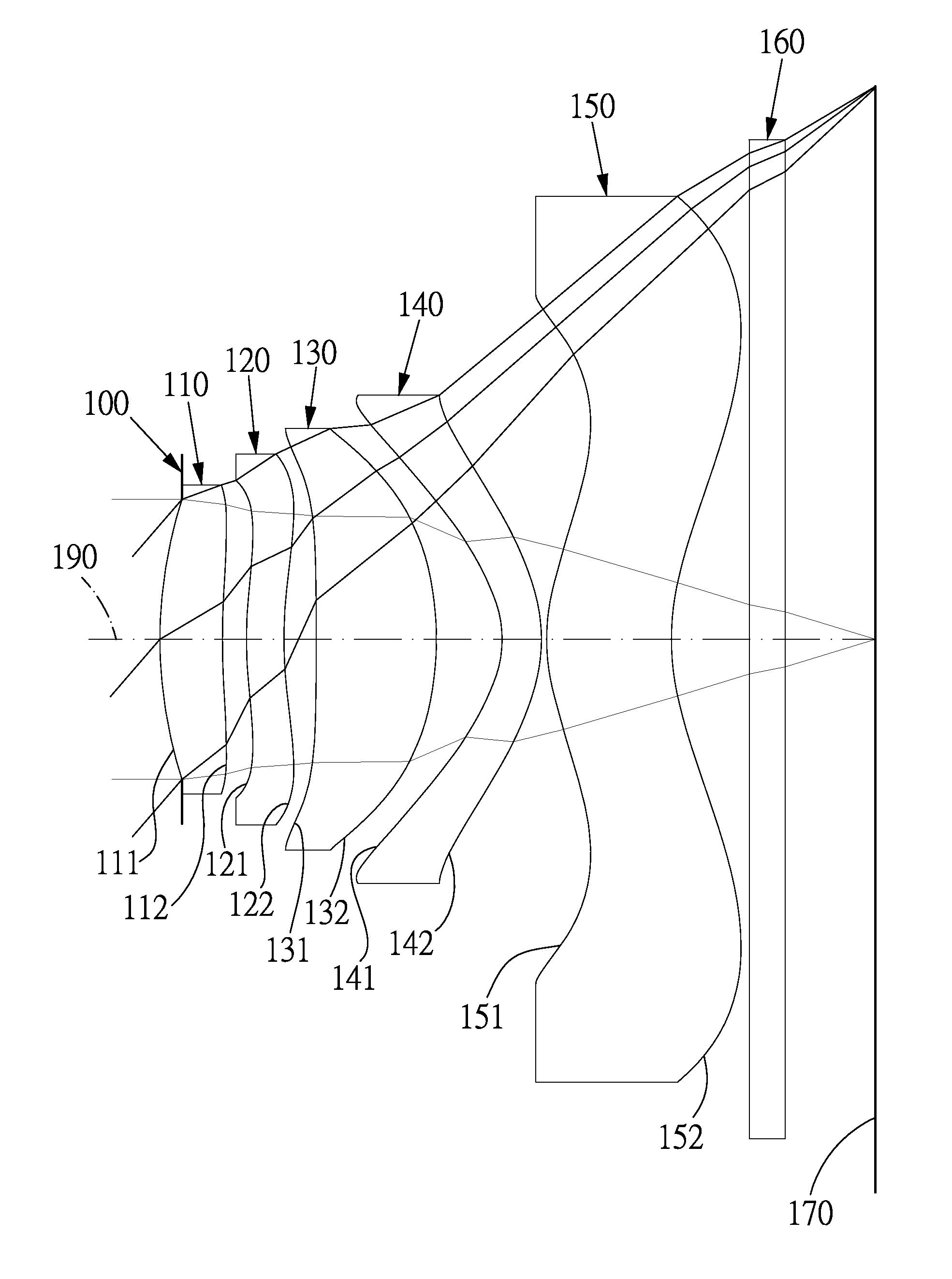
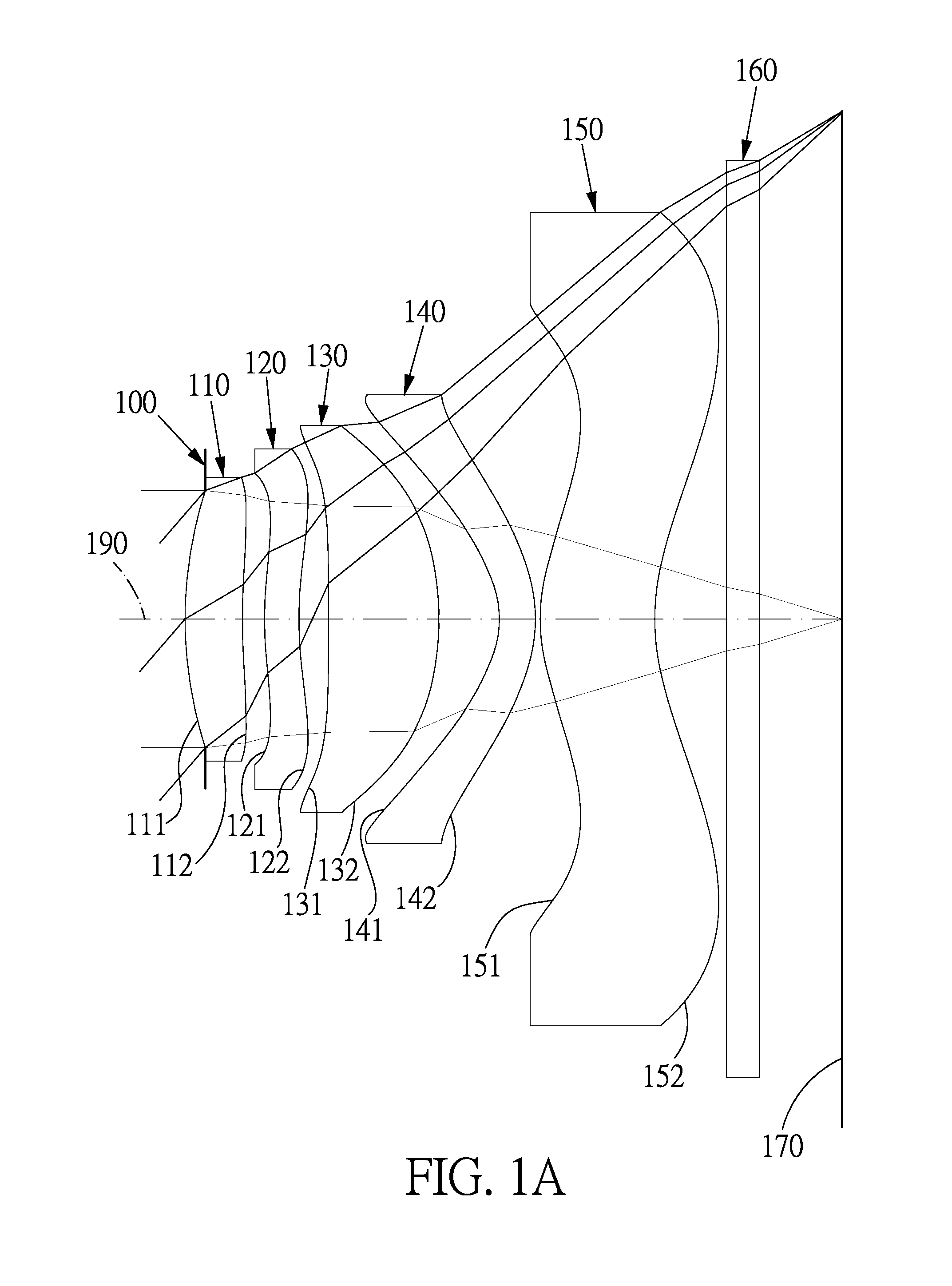
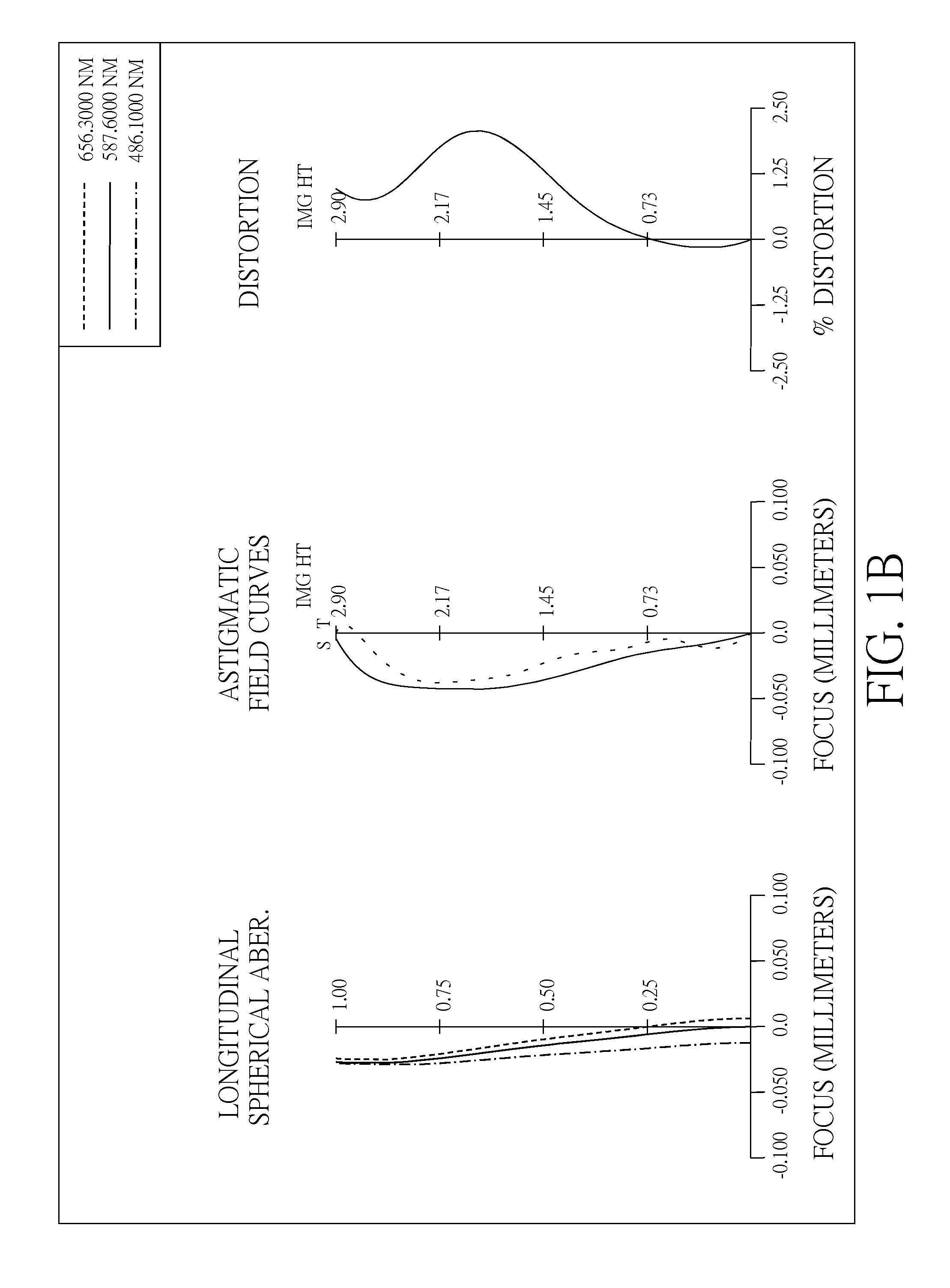
first embodiment
[0064]The equation for the aspheric surface profiles of the first embodiment is expressed as follows:
[0065]z(h)=ch21+1-(1+k)c2h2+A4h4+A6h6+A8h8+A10h10+A12h12+A14h14+…
[0066]z represents the distance of a point on the aspheric surface at a height h from the optical axis 190 relative to a plane perpendicular to the optical axis at the vertex of the aspheric surface;
[0067]c is a paraxial curvature equal to 1 / R (R: a paraxial radius of curvature);
[0068]h represents a vertical distance from the point on the curve of the aspheric surface to the optical axis 190;
[0069]k represents the conic constant;
[0070]A4, A6, A8, A10, A12, A14 . . . : present the high-order aspheric coefficients.
[0071]In the first embodiment of the present imaging lens, the focal length of the imaging lens is f, the f-number of the imaging lens is Fno, half of the maximal field of view of the imaging lens is HFOV, and the following conditions are satisfied:
f=2.803 mm; Fno=1.9, and HFOV=45.97 degrees.
[0072]In th...
second embodiment
[0094]The detailed optical data of the second embodiment is shown in Table 3 and the aspheric surface data is shown in Table 4 below.
[0095]
TABLE 3(Embodiment 2)f(focal length) = 2.828 mm, Fno = 1.9, HFOV = 45.72 deg.FocalSurfaceCurvature RadiusThickness MaterialindexAbbe #length0ObjectPlaneInfinity1(ApertureLens 12.200(ASP)0.37Plastic1.53355.7 8.258stop)24.140(ASP)0.133Lens 21.859(ASP)0.20Plastic1.63223.4102.74041.834(ASP)0.205Lens 3−90.000(ASP)0.77Plastic1.53355.7 2.8346−1.491(ASP)0.397Lens 4−0.519(ASP)0.27Plastic1.65021.4−2.8968−0.864(ASP)0.039Lens 50.899(ASP)0.73Plastic1.53355.7 3.822101.151(ASP)0.4911IR-FilterPlane0.21Glass1.51764.2—12Plane0.5513ImagePlane—
[0096]
TABLE 4Aspheric CoefficientsSurface #12345k =−6.1095E+00−1.0000E+01−2.7102E+00 9.3696E−01 4.0000E+01A4 = 3.9352E−02−1.8857E−01−3.5187E−01−2.7244E−01−7.7331E−02A6 = 1.0688E−01 1.4550E−01 5.8448E−02−1.2729E−01−6.0671E−02A8 =−4.2229E−01−1.9306E−01−1.4023E−01 1.1551E−01−6.2482E−02A10 = 5.0036E−01 9.5114E−02−5.4552E−01 3.6482...
third embodiment
[0107]The detailed optical data of the third embodiment is shown in Table 5 and the aspheric surface data is shown in Table 6 below.
[0108]
TABLE 5(Embodiment 3)f(focal length) = 2.68 mm, Fno = 1.9, HFOV = 47.26 deg.FocalSurfaceCurvature RadiusThickness MaterialindexAbbe #length0ObjectPlaneInfinity1(ApertureLens 12.318(ASP)0.34Plastic1.53355.710.397stop)23.780(ASP)0.103Lens 21.742(ASP)0.25Plastic1.54455.9 20.06541.966(ASP)0.195Lens 319.186(ASP)0.79Plastic1.53355.72.6296−1.491(ASP)0.267Lens 4−0.464(ASP)0.28Plastic1.65021.4−2.3118−0.831(ASP)0.039Lens 50.892(ASP)0.86Plastic1.53355.72.924101.386(ASP)0.4811IR-filterPlane0.21Glass1.517 64.2—12Plane0.5013ImagePlane—
[0109]
TABLE 6Aspheric CoefficientsSurface #12345k =−5.9390E+00−1.0000E+01−2.6466E+00 1.2263E+00 5.0000E+01A4 = 1.8721E−02−2.5731E−01−3.4137E−01−1.7168E−01−4.6447E−02A6 = 8.7992E−02 2.1840E−01 8.7612E−02−1.9879E−01−1.5991E−02A8 =−3.5098E−01−2.3439E−01−1.6378E−01 1.2509E−01−5.9608E−02A10 = 3.9236E−01 5.5266E−02−5.2693E−01 6.8480E−02...
PUM
 Abstract
Description
Claims
Application Information