Apparatus and Method for a Bioptic Real Time Video System

a bioptic and video system technology, applied in the field of vision care, can solve the problems of large pixel size, large hmd of peripheral vision via electronic display, and consequent loss of image detail, and achieve the effect of increasing the usability of such a devi

Active Publication Date: 2012-12-06
ESIGHT CORP
View PDF3 Cites 54 Cited by
  • Summary
  • Abstract
  • Description
  • Claims
  • Application Information

AI Technical Summary

Benefits of technology

[0009]The ability to quickly alternate as required by the specific task, between viewing an image presented in the electronic display and viewing the world without the electronic display, enables many possible usage models for an HMD. Furthermore, in an HMD with an integrated camera, the ability to adjust the vertical camera angle for different tasks, viewing objects distant and close for example, significantly increases the usability of such a device. Finally, an HMD whereby the user is able to select the vertical position of the electronic display, in order to tradeoff a comfortable immersive video experience versus maintaining a broad natural field of view enables the HMD to be used in a variety of user applications and postures.

Problems solved by technology

One of the fundamental challenges of HMDs is the tradeoff between the display's Field of View (FOV), being the size of the virtual display as perceived by the wearer, and pixel size.
As one might expect, to achieve a larger FOV with a given pixel resolution (number of pixels), results in a larger pixel size, and consequent loss of image detail.
To provide significant peripheral vision via the electronic display requires an extremely large (and expensive) HMD.

Method used


Image

  • Apparatus and Method for a Bioptic Real Time Video System
  • Apparatus and Method for a Bioptic Real Time Video System
  • Apparatus and Method for a Bioptic Real Time Video System

Examples


Embodiment Construction

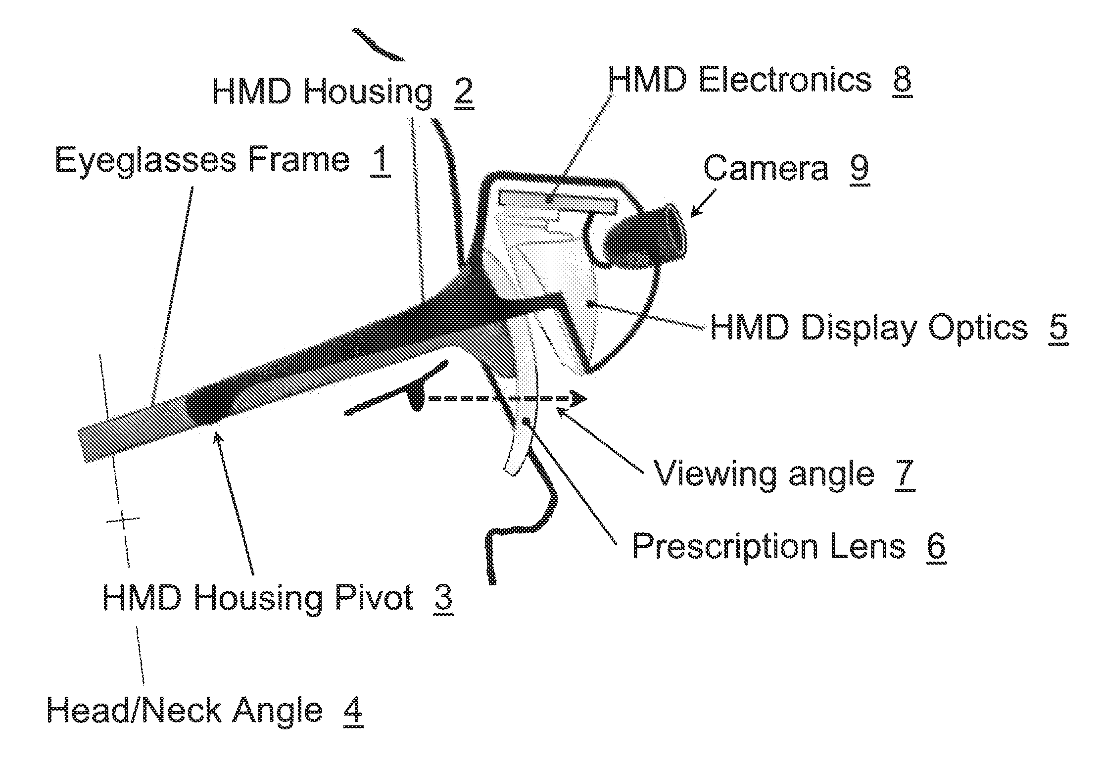
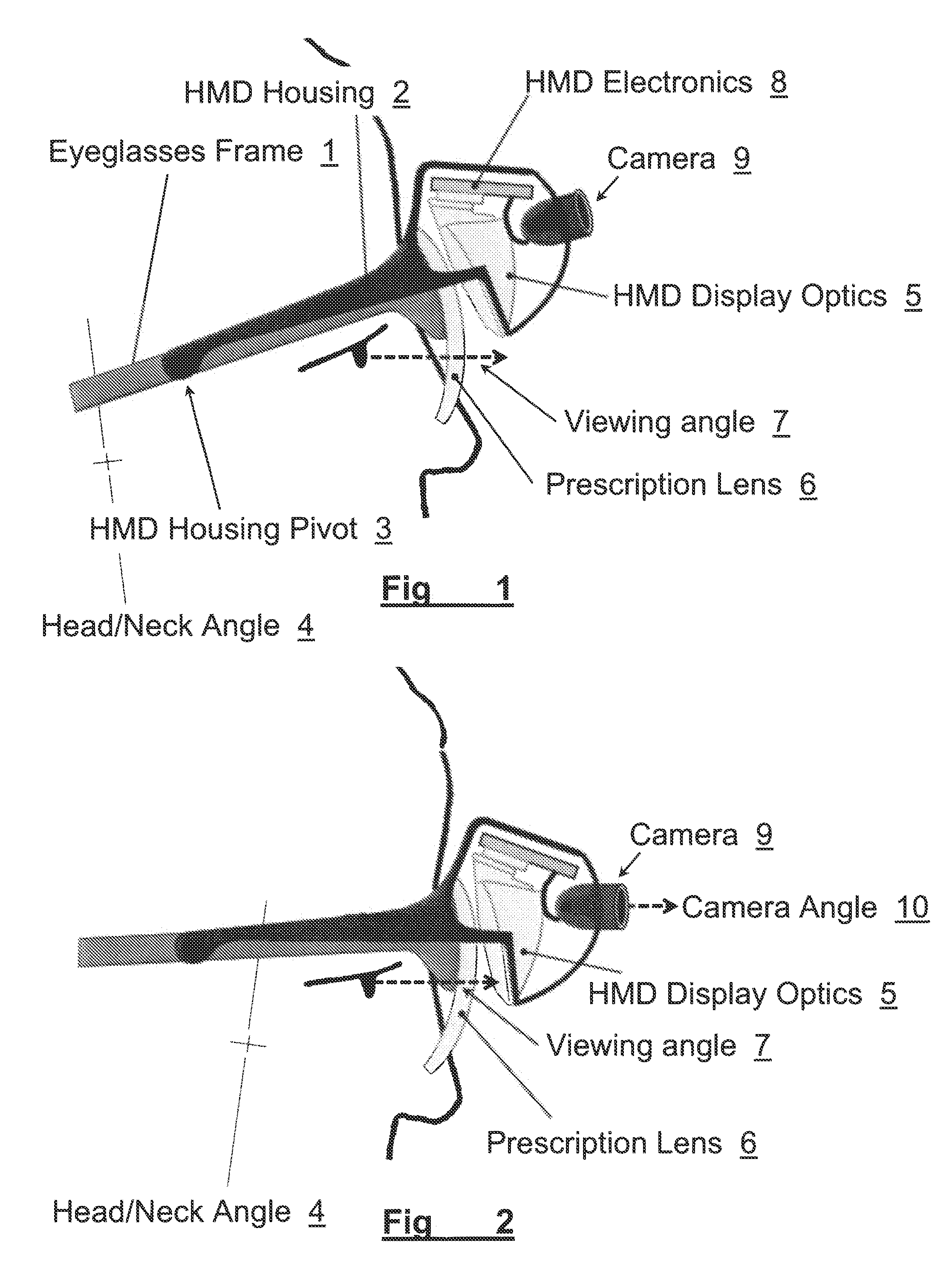
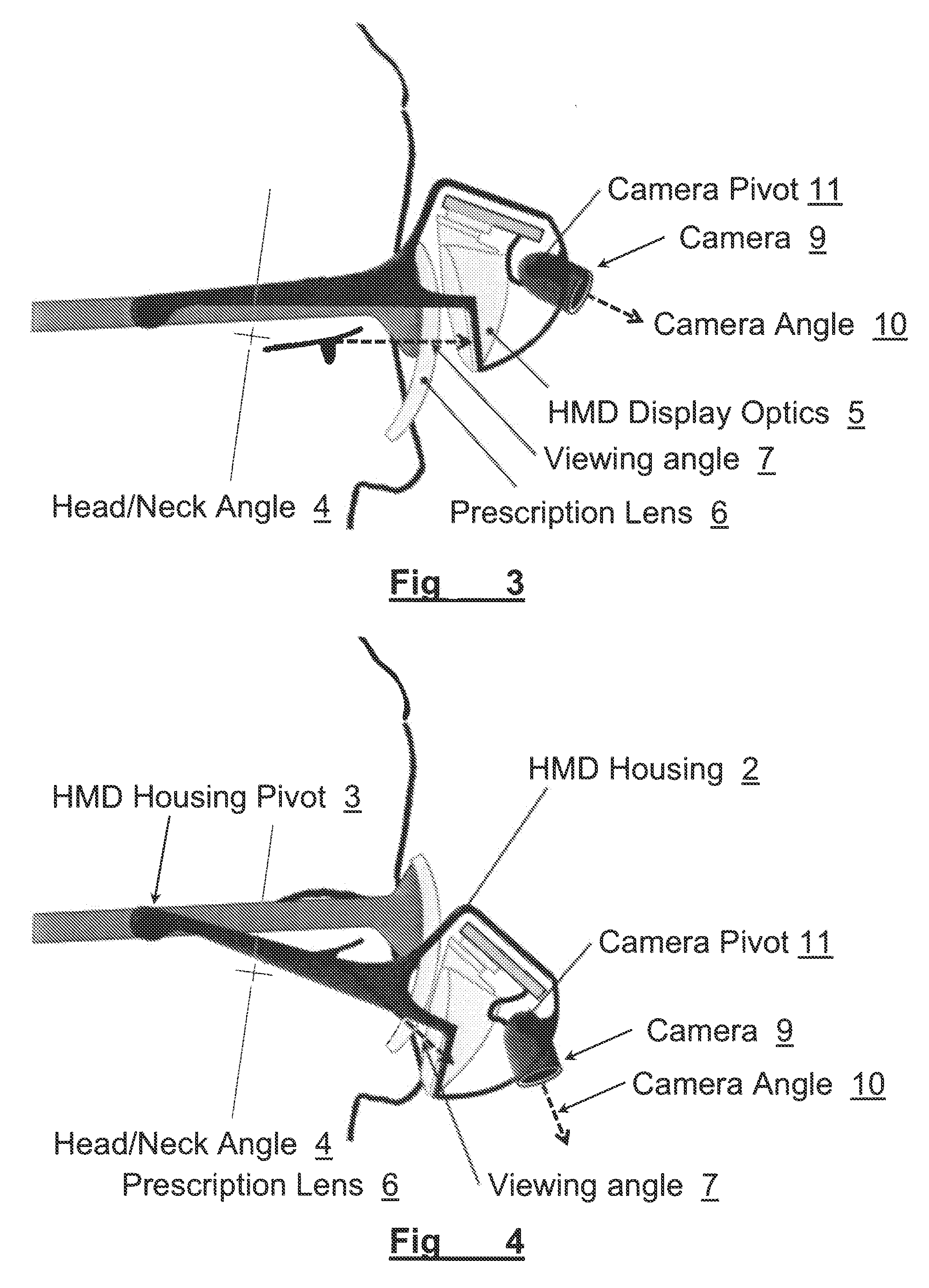
[0023]In brief overview and referring to FIG. 1 and FIG. 6, the system in one embodiment includes prescription lenses 6 mounted to an eyeglasses frame 1. The Head Mounted Display portion of the system comprises a housing 2, which can move relative to the eyeglasses frame 1, about a pivot point 3. The HMD housing 2 incorporates HMD optics 5, a camera 9, and HMD electronics 8 (collectively, the “HMD”).

[0024]In the orientation depicted in FIG. 1, the wearer's head / neck posture is angled slightly back 4, and he is viewing the world 7 through the prescription lens 6, without the use of the HMD optics 5 or camera 9.

[0025]In FIG. 2, the head / neck angle 4 is slightly forward, allowing the user to view the HMD optics 5 through the same prescription lens 6 by directing their gaze at a slight upward angle 7. In this mode, video information viewed through the HMD optics 5 can be provided from the video camera 9, oriented at an outward angle 10 such that objects at a distance can be viewed in th...


PUM


Abstract

A method and apparatus of displaying an electronic video image using a head-worn near-to-eye display in a non-immersive fashion, such that the wearer can choose, through simple adjustments of their neck and eye angles, to either look at the displayed video image or their natural environment. The invention also relates to the incorporation of prescription lenses into the optical chain of the near-to-eye display. The invention also relates to the use of motion and position sensors incorporated into the head-worn device to enable automatic stabilization of the video image. The invention also relates to the use of motion and position sensors incorporated into the head-worn device to automatically adjust the vertical angle of either the camera or the electronic display or both, by sensing the vertical angular position of the user's head.

Description

FIELD OF THE INVENTION[0001]The invention relates generally to the field of wearable electronic displays and more specifically to the field of vision care.BACKGROUND OF THE INVENTION[0002]There are numerous applications for lightweight head-worn near-to-eye displays. These are commonly called Head Mounted Displays (HMD). HMDs display to the eye an electronically rendered image such that the wearer perceives that they are watching a sizeable electronic display at some distance in front of them. The applications that use such HMDs are numerous, including but not limited to virtual reality, electronic gaming, simulation environments such as for military simulations or flight simulators, medical applications such as for the enhancement of sight, and consumer applications such as the ability to view videos in a mobile setting.[0003]One of the fundamental challenges of HMDs is the tradeoff between the display's Field of View (FOV), being the size of the virtual display as perceived by the...

Claims


Application Information

Patent Timeline
Patent Type & Authority Applications(United States)
IPC IPC(8): G09G5/00
CPCG09G5/00G02B27/017G02B2027/0127G02B2027/0138G02B2027/0156G02B2027/0187G02B27/0149G02B27/0176G02B2027/0154
Inventor HILKES, ROBERT G.
Owner ESIGHT CORP
Why Eureka
Try Eureka