

Imaging lens assembly
a technology of imaging lens and assembly, which is applied in the field of imaging lens assembly, can solve the problems of difficult to achieve both miniaturization and high performance on the imaging lens assembly, and achieve the effects of effective shortened total track length, wide field of view, and high performan
- Summary
- Abstract
- Description
- Claims
- Application Information
AI Technical Summary
Benefits of technology
Problems solved by technology
Method used
Image

Examples
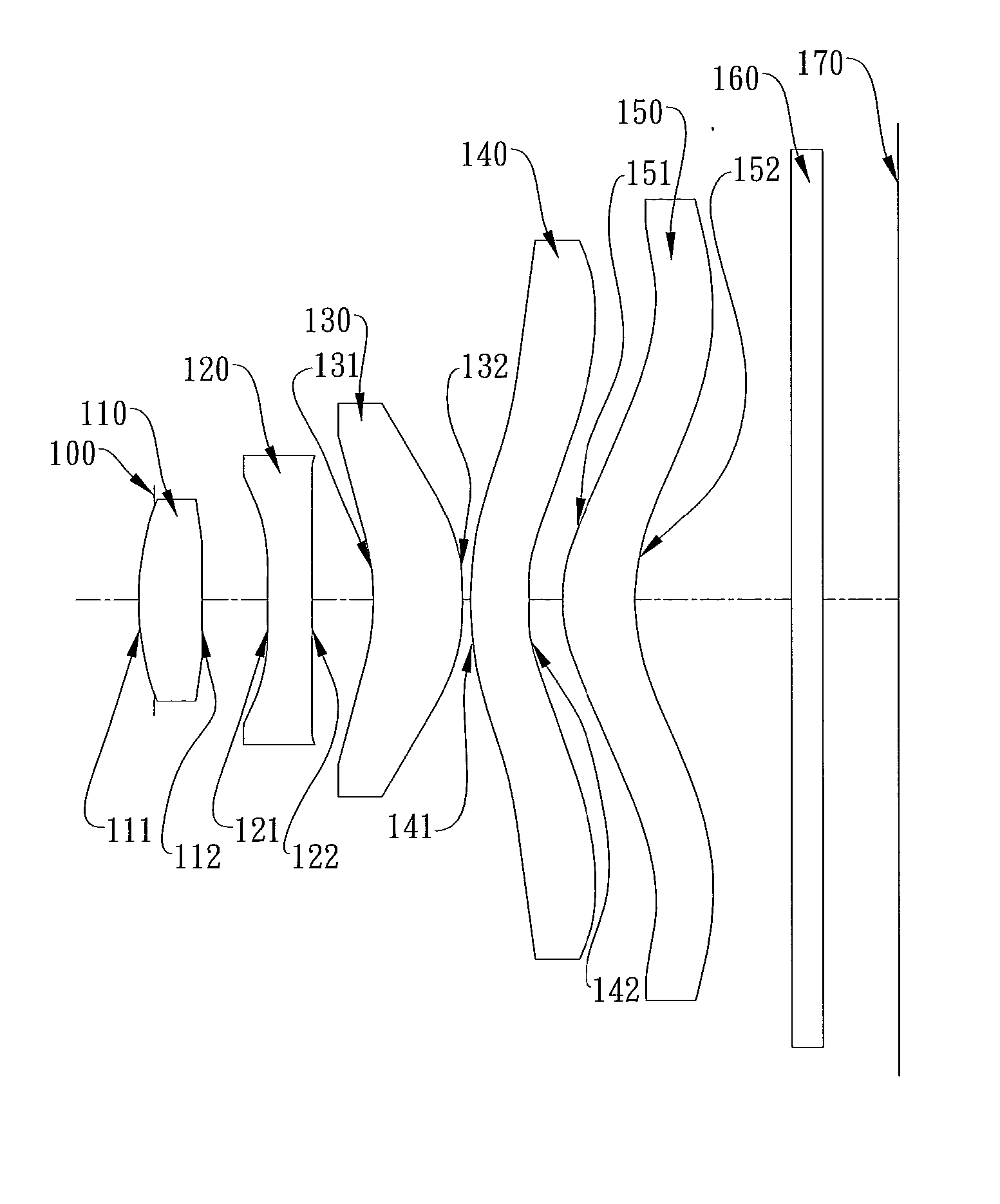
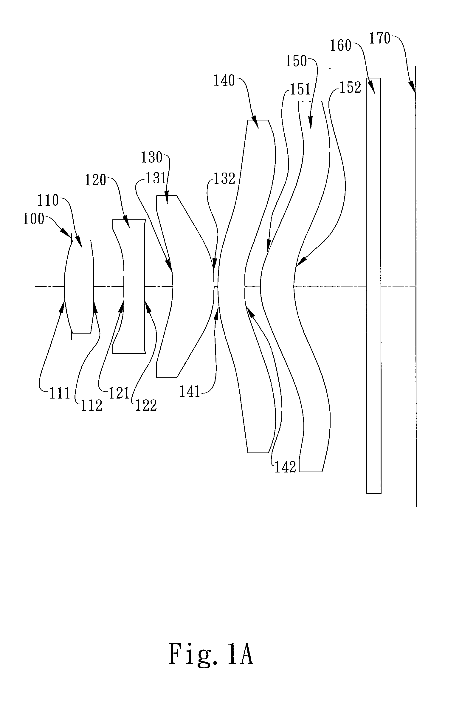
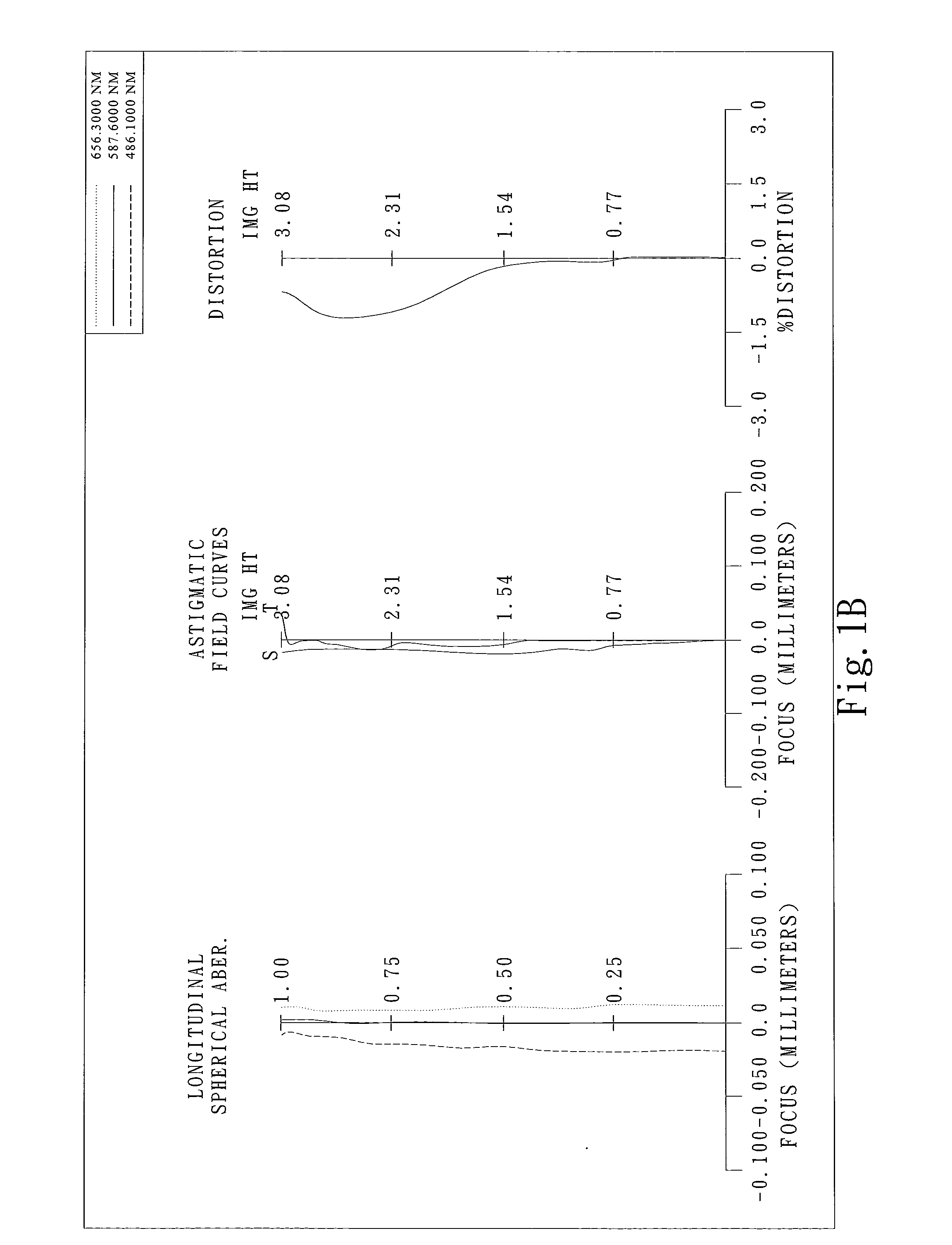
first embodiment
[0058]In the present imaging lens assembly, the focal length of the imaging lens assembly is f, and it satisfies the relation: f=3.63.
[0059]In the first embodiment of the present imaging lens assembly, the f-number of the imaging lens assembly is Fno, and it satisfies the relation: Fno=3.4.
[0060]In the first embodiment of the present imaging lens assembly, half of the maximal field of view of the imaging lens assembly is HFOV, and it satisfies
[0061]the relation: HFOV=40.6 degrees.
[0062]In the first embodiment of the present imaging lens assembly, the Abbe number of the first lens element 110 is v d 1, the Abbe number of the second lens element 120 is v d 2, and they satisfy the relation: v d 1−v d 2=32.5.
[0063]In the first embodiment of the present imaging lens assembly, the radius of curvature of the object-side surface 111 of the first lens element 110 is R1, the radius of curvature of the image-side surface 112 of the first lens element 110 is R2, and they satisfy the relation: R...
second embodiment
[0073]In the present imaging lens assembly, the focal length of the imaging lens assembly is f, and it satisfies the relation: f=3.63.
[0074]In the second embodiment of the present imaging lens assembly, the f-number of the imaging lens assembly is Fno, and it satisfies the relation: Fno=3.4.
[0075]In the second embodiment of the present imaging lens assembly, half of the maximal field of view of the imaging lens assembly is HFOV, and it satisfies the relation: HFOV=39.7 degrees.
[0076]In the second embodiment of the present imaging lens assembly, the Abbe number of the first lens element 210 is v d 1, the Abbe number of the second lens element 220 is v d 2, and they satisfy the relation: v d 1−v d 2=32.5.
[0077]In the second embodiment of the present imaging lens assembly, the radius of curvature of the object-side surface 211 of the first lens element 210 is R1, the radius of curvature of the image-side surface 212 of the first lens element 210 is R2, and they satisfy the relation: R1...
third embodiment
[0087]In the present imaging lens assembly, the focal length of the imaging lens assembly is f, and it satisfies the relation: f=3.63.
[0088]In the third embodiment of the present imaging lens assembly, the f-number of the imaging lens assembly is Fno, and it satisfies the relation: Fno=2.8.
[0089]In the third embodiment of the present imaging lens assembly, half of the maximal field of view of the imaging lens assembly is HFOV, and it satisfies the relation: HFOV=40.3 degrees.
[0090]In the third embodiment of the present imaging lens assembly, the Abbe number of the first lens element 310 is v d 1, the Abbe number of the second lens element 320 is v d 2, and they satisfy the relation: v d 1−v d 2=32.5.
[0091]In the third embodiment of the present imaging lens assembly, the radius of curvature of the object-side surface 311 of the first lens element 310 is R1, the radius of curvature of the image-side surface 312 of the first lens element 310 is R2, and they satisfy the relation: R1 / R2=...
PUM
 Abstract
Description
Claims
Application Information