Magnus rotor comprising a guide roller cover

a technology of a guide roller and a rotor, which is applied in the direction of marine propulsion, special-purpose vessels, vessel construction, etc., can solve the problems of slipping of the adder or the working platform out of position, and achieve the effect of reducing the risk of slipping and preventing slipping

Active Publication Date: 2015-11-17
WOBBEN PROPERTIES GMBH
View PDF23 Cites 4 Cited by
  • Summary
  • Abstract
  • Description
  • Claims
  • Application Information

AI Technical Summary

Benefits of technology

[0010]There is described a Magnus rotor having a carrier arranged in the interior of the Magnus rotor. The Magnus rotor has a rotor which rotates about the carrier in operation of the Magnus rotor. A bearing carries the rotor on the carrier. Beneath its guide rollers the Magnus rotor has a respective walkway surface which is also covered and protected when the cover is pivoted up. In the downwardly pivoted condition the cover exposes both the guide roller on which operations are to be effected and also the walkway surface thereof so that this surface can be walked upon or used for carrying out the operation and the operating personnel can safely perform maintenance or replacement from that walkway surface.
[0011]An advantage of that walkway surface is that this avoids the necessity for the personnel having to establish access to the corresponding guide roller for maintenance or replacement operations, by way of a ladder or working platform. It is precisely on the deck of a ship that such a ladder or working platform could be safeguarded against slipping or movement, only at a major level of complication and expenditure. In addition, in the case of a ship's deck which is always wet due to rain and spray it is never possible to completely eliminate the risk of slipping, which also causes for example ladders or working platforms to slip out of position. Thus ladders, working platforms and similar aids for reaching a guide roller always represent a source of danger to the operating personnel, which according to the invention can be avoided by the walkway surface provided beneath or beside the guide roller. In addition, beside a cover in the downwardly folded condition, there may be no space or scarcely any space to position a ladder or working platform there, or at least in such a way that access to the guide roller to be able to carry out the operations is possible therefrom. In addition, setting up and removing a ladder or a working platform represents additional complication which can be avoided by the provision of an integrated walkway surface. Thus the provision of the walkway surface according to the invention under the guide roller means that the operation in itself is not only safer but can also be carried out more easily and with a greater saving of time.
[0013]In a further aspect of the invention the walkway surface is provided with a surface or the surface is coated to prevent slipping on the walkway surface. That is advantageous to reduce the risk of slipping when walking on the walkway surface or standing thereon as it is precisely when carrying out operations on a ship's deck that the operating personnel is seriously endangered by tripping over or falling, for example by falling overboard.
[0014]In an aspect of the invention the cover has a motion device which is adapted to hold the cover in the opened condition at a vertical height above the walkway surface. That motion device on the one hand permits the cover or each cover segment to be folded up and down. On the other hand, that prevents the cover segment from being folded down or dropping down completely onto the underlying surface or the ship's deck as the cover segment can be held at a given height above the underlying surface or ship's deck by the motion device. In that case it is advantageous for that given height to be so selected that the cover segment is positioned at least partially above the walkway surface. That arrangement can provide that the cover segment in the folded-down condition affords protection for preventing a person who is on the walkway surface from falling onto the underlying surface or the ship's deck.
[0015]In a further aspect of the invention the motion device is adapted, in the opened condition of the cover, to extend in a substantially radial direction of the Magnus rotor from same to the opened cover above the walkway surface. As a result of that arrangement the folded-down cover rearwardly and / or the motion device towards the sides jointly or in each case alone form protection against a person on the walkway surface from falling down. That arrangement so-to-speak forms a working pulpit to afford a person on the walkway surface protection against falling down in all directions.
[0016]In an aspect of the invention the motion device is secured in the closed condition of the cover by means of an arresting device. That is advantageous as the cover can be secured by that arresting means and can be secured against accidental downward pivotal movement, that is to say opening, in particular when a ship on which the Magnus rotor is used is subject to a heavy swell. In addition each segment of the cover can be opened individually, that is to say pivoted downwardly, by means of that arresting arrangement. That arresting arrangement is advantageously accessible from the exterior and is to be quickly and easily operated without auxiliary means and tools, for example by a rotary movement through 90°.

Problems solved by technology

In addition, in the case of a ship's deck which is always wet due to rain and spray it is never possible to completely eliminate the risk of slipping, which also causes for example ladders or working platforms to slip out of position.

Method used


Image

  • Magnus rotor comprising a guide roller cover
  • Magnus rotor comprising a guide roller cover
  • Magnus rotor comprising a guide roller cover

Examples


Embodiment Construction

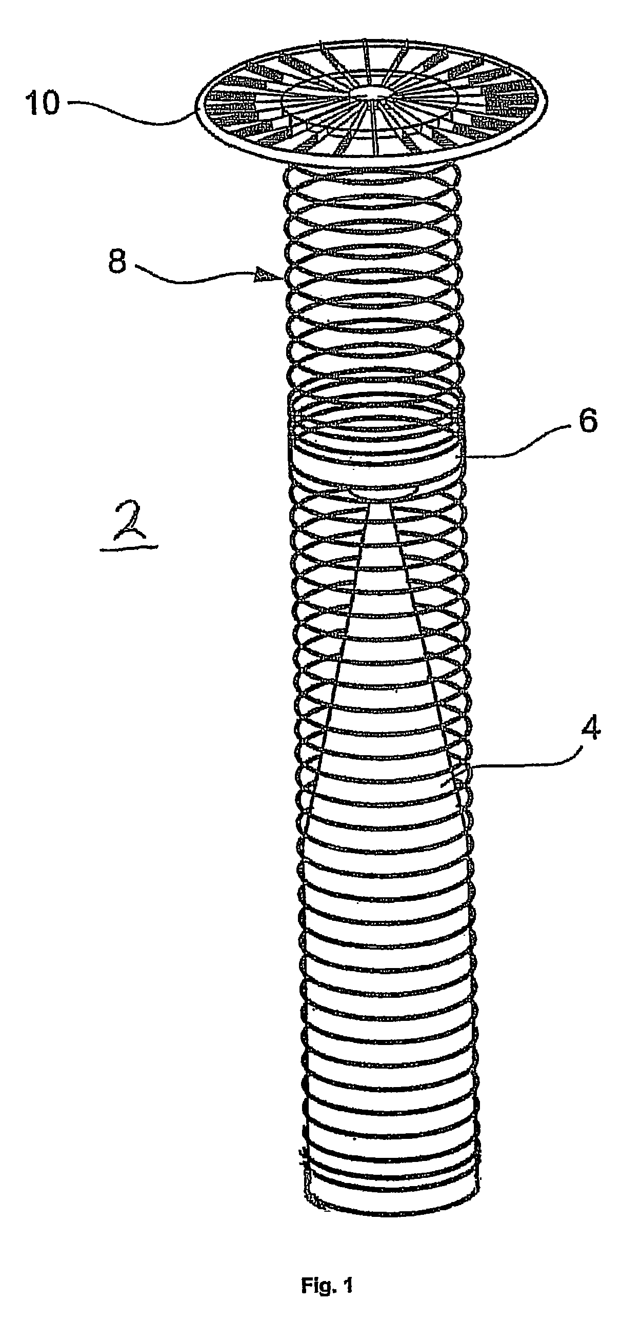
[0028]FIG. 1 shows a diagrammatic perspective view of a Magnus rotor 2. The Magnus rotor 2 has a rotor 8 which is preferably cylindrical. An end plate 10 is mounted at the upper end of the rotor 8. Insofar as the Magnus rotor 2 is mounted on a base plate (not shown) such as for example a ship's deck or the like, a corresponding end plate is not required at its lower end as that is formed by the base plate or the deck itself. The rotor 8 is carried by a carrier 4 which is arranged in the interior of the rotor 8 and on which the rotor 8 rotates, by way of a bearing 6. The bearing 6 can be a known rolling bearing or any other suitable bearing configuration.

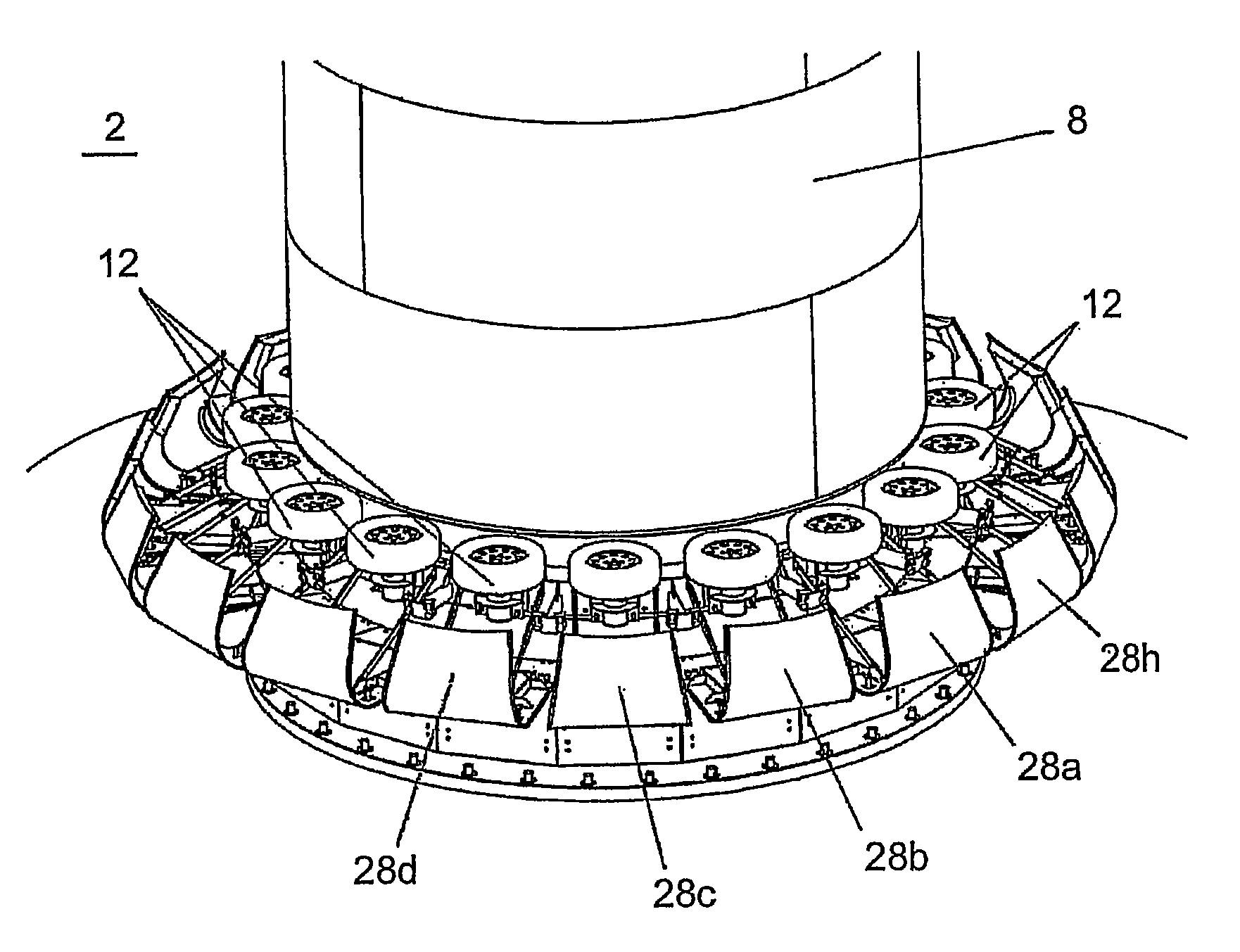
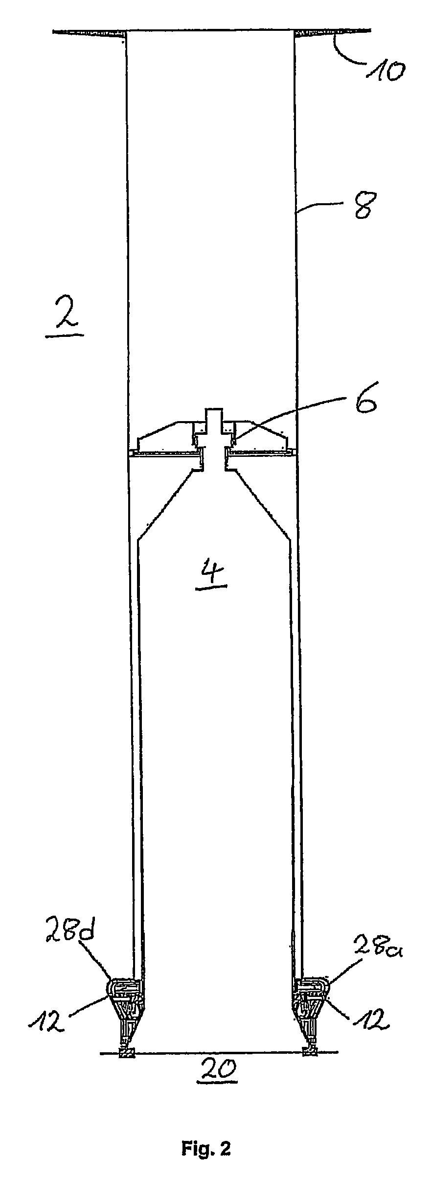
[0029]FIG. 2 shows a diagrammatic simplified side view of a Magnus rotor 2 with inwardly disposed carrier 4, the upwardly disposed rotor 8, the bearing 6 and the end plate 10. The Magnus rotor 2 is fixed on an underlying base structure 20 which can be a base plate, a ship's deck or the like. In addition FIG. 2 shows guide rollers 12 ...


PUM


Abstract

The present invention concerns a Magnus rotor comprising a guide roller which is arranged at the lower outer periphery of the Magnus rotor and which bears against the Magnus rotor in play-free relationship, a walkway surface arranged beneath the guide roller, and a cover which covers the guide roller and the walkway surface. In an opened condition the cover exposes the guide roller and the walkway surface so that a person on the walkway surface can perform working operations at the guide roller.

Description

BACKGROUND[0001]1. Technical Field[0002]The present invention concerns a Magnus rotor having a guide roller cover.[0003]2. Description of the Related Art[0004]Magnus rotors are also referred to as Flettner rotors or sailing rotors.[0005]Magnus rotors are known in the state of the art. Particularly as ship drives, they have also become known by the term Flettner rotors and equipping ships with such a Flettner rotor or Magnus rotor is described in the book “Die Segelmaschine” by Klaus D. Wagner which appeared in Ernst Kabel Verlag GmbH, Hamburg, 1991.[0006]CH 116268 discloses a Magnus rotor having a guide with a plurality of guide wheels. The guide rollers can be arranged within the Magnus rotor and support it from the interior or also outside it in order to support the Magnus rotor from the exterior. Resilient tires like the wheels of motor vehicles are used as the guide rollers.[0007]WO 2006 / 137844 A2 discloses a Magnus rotor having at least three guide rollers which are arranged at...

Claims


Application Information

Patent Timeline
Patent Type & Authority Patents(United States)
IPC IPC(8): B63H9/02
CPCB63H9/02Y02T70/58Y02T70/5236
Inventor ROHDEN, ROLF
Owner WOBBEN PROPERTIES GMBH
Why Eureka
Try Eureka