
Wellbore gun perforating system and method

a perforating system and wellbore technology, applied in the field of oil and gas extraction, can solve the problems of failure, potential error during any part of the assembly process, and the inability to cut the detonating cord to the correct siz

Active Publication Date: 2015-11-24
WELLS FARGO BANK NAT ASSOC +1
View PDF23 Cites 90 Cited by
  • Summary
  • Abstract
  • Description
  • Claims
  • Application Information

AI Technical Summary

Benefits of technology

The present invention is a system for use in gas extraction from wellbores that includes a gun string assembly with multiple perforating guns attached to switch subs. The switch subs have pre-wired electrical contacts that connect to the perforating guns without the need for manual field assembly. The system also includes a detonator positioned upstream of the perforating guns and a switch positioned downstream of the perforating guns. The system is controlled by a method that involves attaching wired switch subs to the perforating guns and deploying the gun string assembly into the wellbore casing with a wireline. The method then proceeds to fire the perforating guns and activate the switches. The system allows for automated and efficient gas extraction from wellbores.

Problems solved by technology

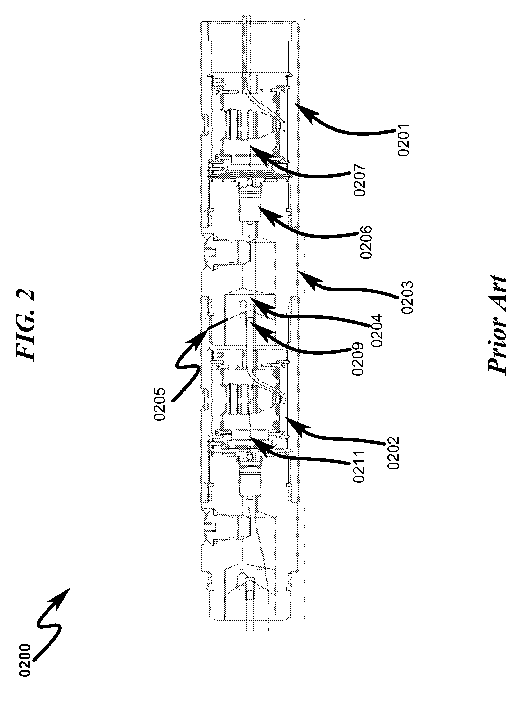
There is potential for error during any part of the assembly process.
The wires are cut and packed into a sub port manually, which has potential for failure.
There is a potential that the detonating cord is not cut to the correct size and a potential for an open connection.
This is especially true for electronic switches.(3) Making electrical connections (0303);The connections are made manually in the field and may cause undesired shorts or opens.
There is a potential for missing one gun in the assembly, in which case the whole gun string assembly has to be pulled out.(4) Installing the switch (0304);(5) Sorting, crimping and cutting the wires (0305); There is a potential for failure in the process.(6) Coiling and packing the wires into the sub through the sub port (0306); andOnce the detonator is armed, any voltage source to the detonator can cause the gun to misfire.
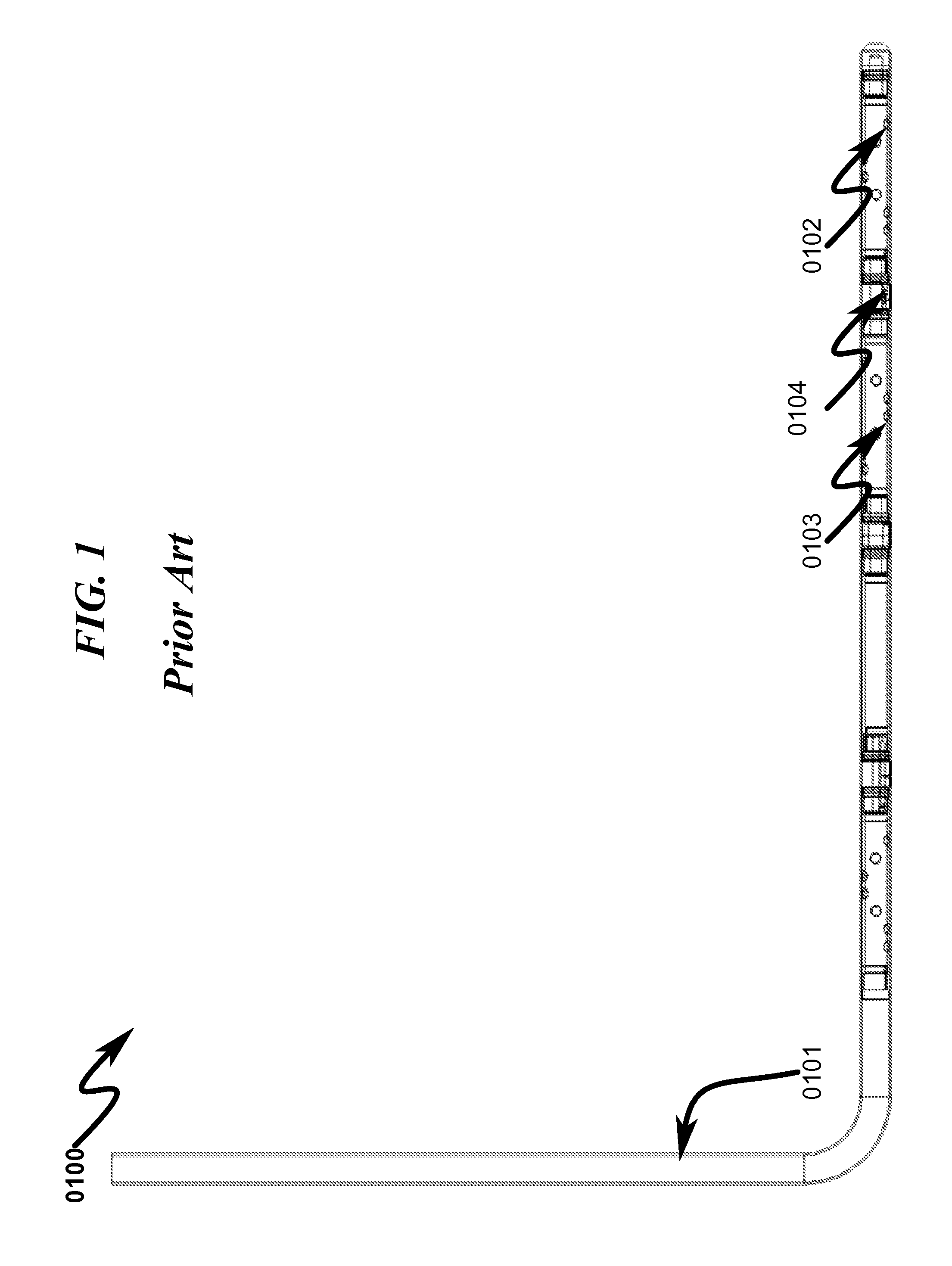
The prior art as detailed above suffers from the following deficiencies:Prior art systems do not provide for reliable connection mechanism needed to perforate hydrocarbon formations with a gun string assembly.Prior art systems do not provide for a pre-wired perforating gun and switch sub system that does not require manual wiring connections.Prior art systems do not provide for a connection mechanism with no manual connection steps.Prior art systems do not provide for a reliable ground wire for the detonator in a perforating gun system for the detonation to function as desired.
While some of the prior art may teach some solutions to several of these problems, the core issue of reacting to unsafe gun pressure has not been addressed by prior art.

Method used


Image

  • Wellbore gun perforating system and method
  • Wellbore gun perforating system and method
  • Wellbore gun perforating system and method

Examples


Embodiment Construction

[0079]While this invention is susceptible to embodiment in many different forms, there are shown in the drawings and will herein be described in detail a preferred embodiment of the invention with the understanding that the present disclosure is to be considered as an exemplification of the principles of the invention and is not intended to limit the broad aspect of the invention to the embodiment illustrated.

[0080]The numerous innovative teachings of the present application will be described, with particular reference to the presently preferred embodiment, wherein these innovative teachings are advantageously applied to the particular problems of a wellbore gun perforating system and method. However, it should be understood that this embodiment is only one example of the many advantageous uses of the innovative teachings herein. In general, statements made in the specification of the present application do not necessarily limit any of the various claimed inventions. Moreover, some ...


PUM


Abstract

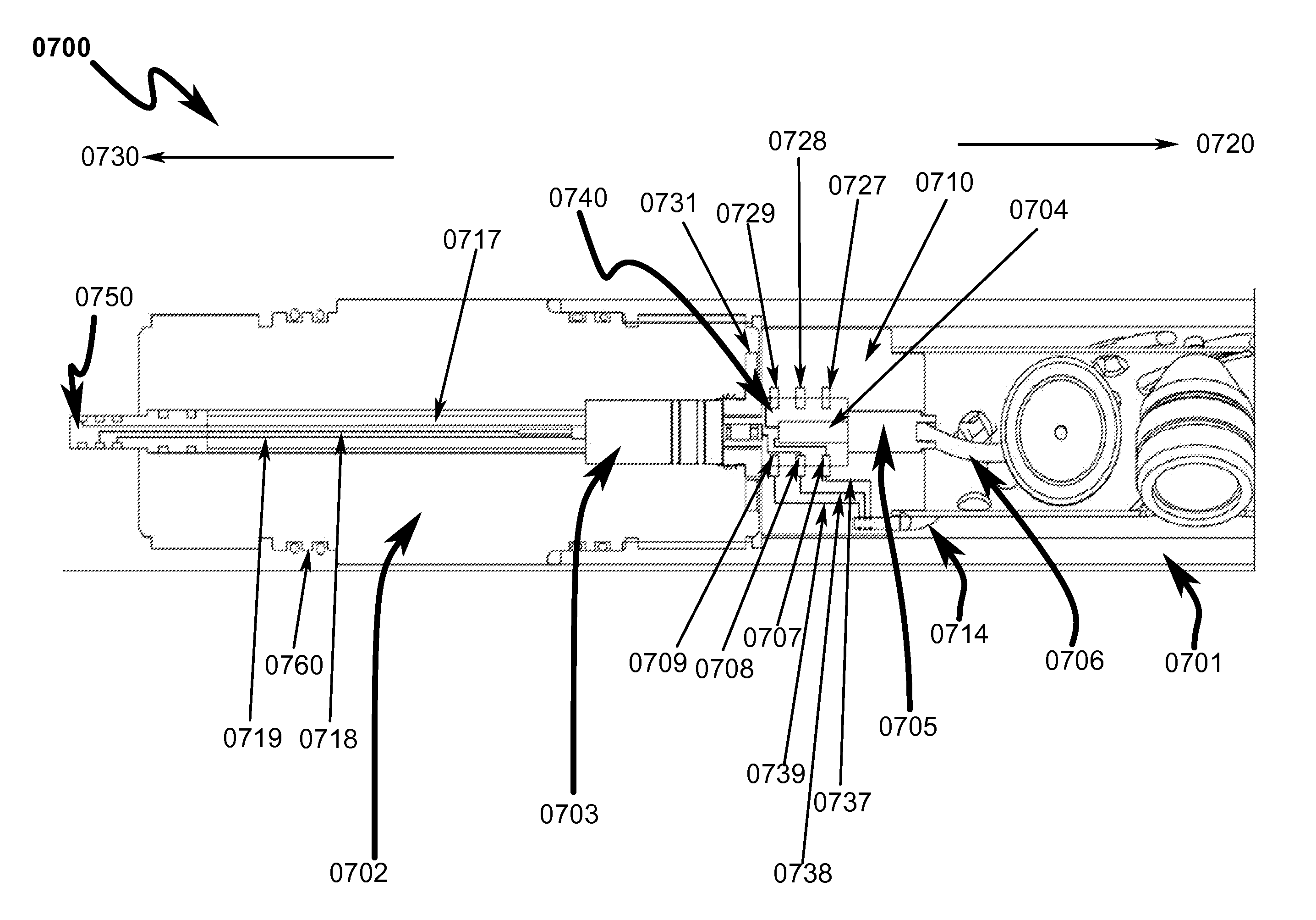
A wellbore perforating system and method with reliable and safer connections in a perforating gun assembly is disclosed. The system / method includes a gun string assembly (GSA) deployed in a wellbore with multiple perforating guns attached to plural switch subs. The perforating guns are pre-wired with a cable having multi conductors; the multi conductors are connected to electrical ring contacts on either end of the perforating guns. The switch subs are configured with electrical contacts that are attached to the electrical contacts of the perforating guns without the need for manual electrical connections and assembly in the field of operations. The system further includes detonating with a detonator that is positioned upstream of the perforating gun. The detonator is wired to a switch that is positioned downstream of the perforating gun.

Description

CROSS REFERENCE TO RELATED APPLICATIONS[0001]Not ApplicablePARTIAL WAIVER OF COPYRIGHT[0002]All of the material in this patent application is subject to copyright protection under the copyright laws of the United States and of other countries. As of the first effective filing date of the present application, this material is protected as unpublished material.[0003]However, permission to copy this material is hereby granted to the extent that the copyright owner has no objection to the facsimile reproduction by anyone of the patent documentation or patent disclosure, as it appears in the United States Patent and Trademark Office patent file or records, but otherwise reserves all copyright rights whatsoever.STATEMENT REGARDING FEDERALLY SPONSORED RESEARCH OR DEVELOPMENT[0004]Not ApplicableREFERENCE TO A MICROFICHE APPENDIX[0005]Not ApplicableFIELD OF THE INVENTION[0006]The present invention generally relates to oil and gas extraction. Specifically, the invention attempts to pre-wire a...

Claims


Application Information

Patent Timeline
Patent Type & Authority Patents(United States)
IPC IPC(8): E21B43/11F42D1/06F42D1/055F42D1/04F42D1/045E21B29/02E21B43/116F42D1/05E21B43/1185F42B3/00
CPCF42D1/05F42D1/06F42D1/04F42D1/045E21B43/1185F42D1/055E21B43/116E21B29/02F42B3/00E21B43/119E21B43/117
Inventor HARDESTY, JOHN T.ROLLINS, JAMES A.
Owner WELLS FARGO BANK NAT ASSOC
Learn More