
Electro-hydraulic actuator with an integrated brake

a technology of electrohydraulic actuators and brakes, which is applied in the direction of couplings, braking systems, dynamo-electric machines, etc., can solve the problems of high energy consumption and high thermal dissipation, and achieve high energy consumption, high holding torque mode, and without overheating

Inactive Publication Date: 2015-11-24
JOHNSON ELECTRIC SA
View PDF9 Cites 0 Cited by
  • Summary
  • Abstract
  • Description
  • Claims
  • Application Information

AI Technical Summary

Benefits of technology

[0005]Hence, there is a desire for an electro-hydraulic actuator that is able to be operated in high holding torque mode for long periods of time without overheating and without having high energy consumption.
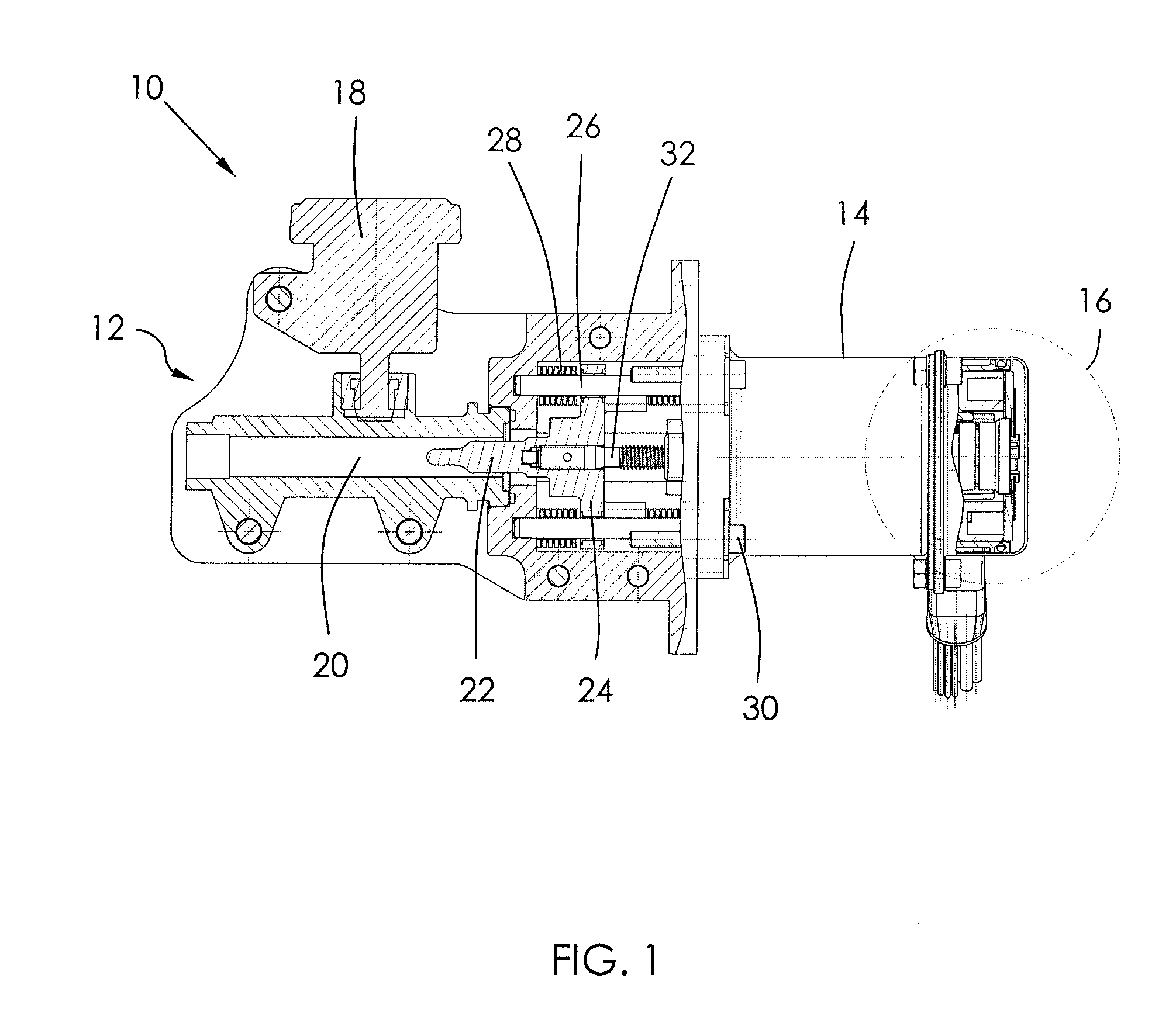
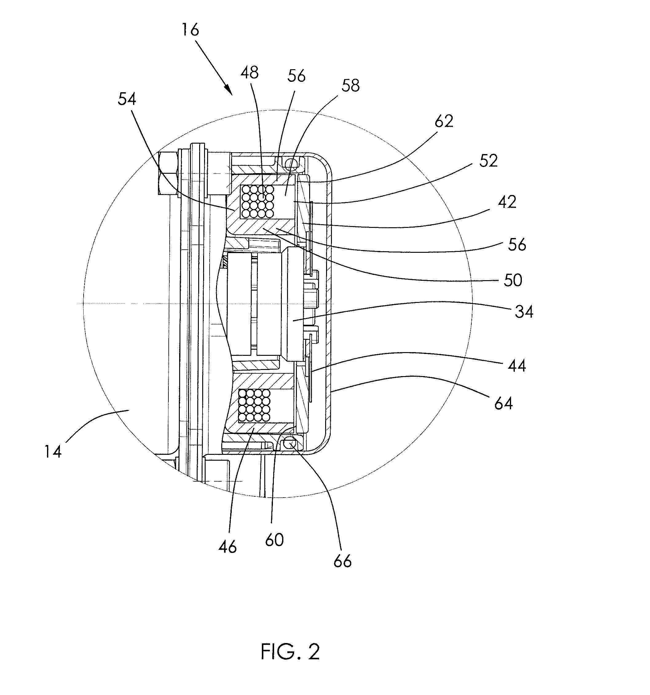
[0007]Accordingly, in one aspect thereof, the present invention provides an electro-hydraulic actuator for a hydraulic circuit comprising: a master cylinder comprising a hydraulic cylinder and an actuation piston slidably received within the hydraulic cylinder to vary pressure within the hydraulic circuit; an electric motor adapted to drive the actuation piston into the hydraulic cylinder, the motor comprising a stator and a rotor; and an electro-mechanical brake arranged to selectively and releasably hold the rotor with respect to the stator to prevent relative rotational motion there between.

Problems solved by technology

If this holding torque needs to be provided by the motor, a high current level is required to be maintained, resulting in high energy consumption and high thermal dissipation which may lead eventually to overheating.

Method used


Image

  • Electro-hydraulic actuator with an integrated brake
  • Electro-hydraulic actuator with an integrated brake
  • Electro-hydraulic actuator with an integrated brake

Examples


Embodiment Construction

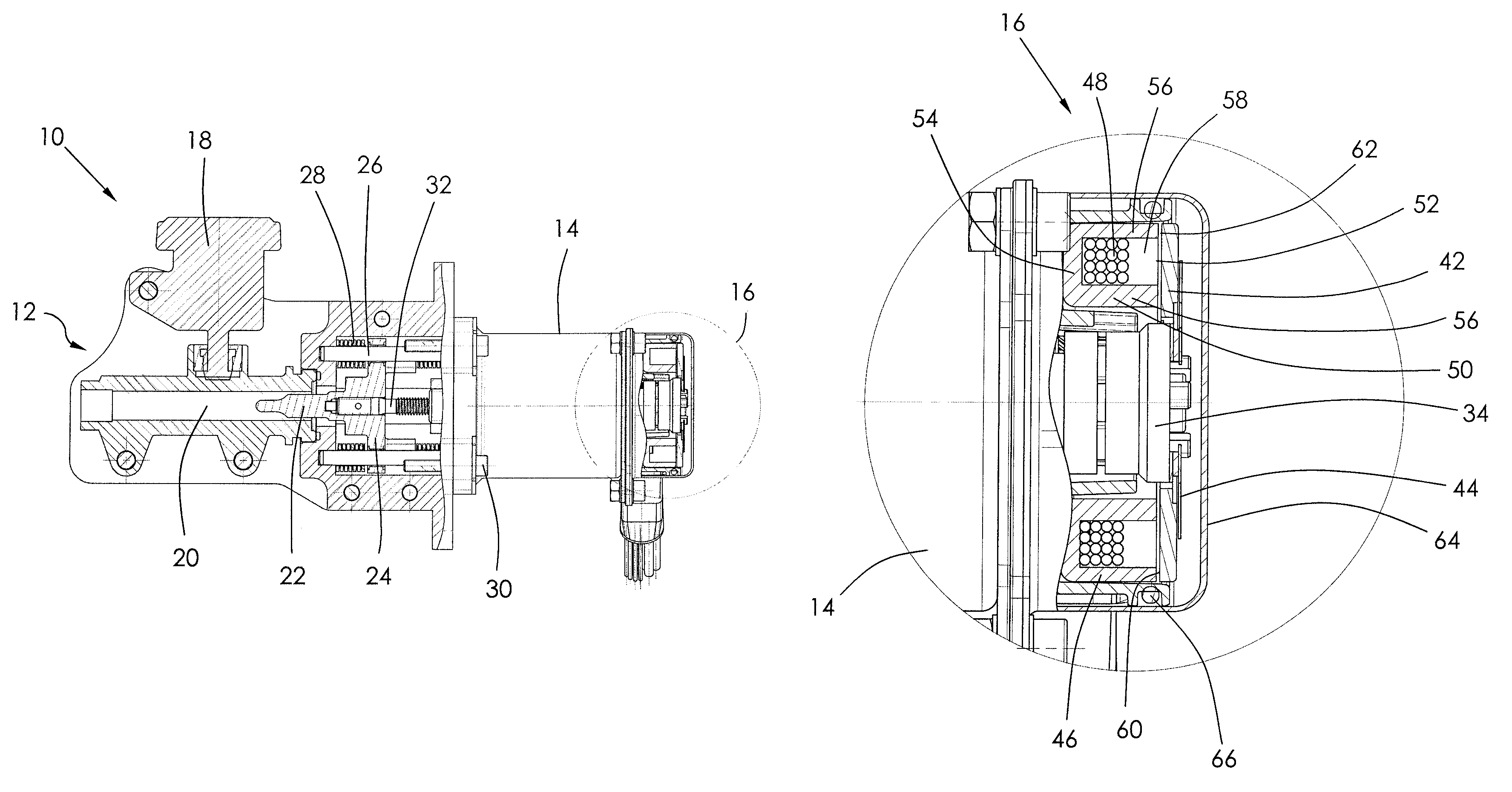
[0022]FIG. 1 illustrates, in partial section, an electro-hydraulic actuator 10 in accordance with the preferred embodiment of the present invention. The actuator 10 comprises a master cylinder 12, an electric motor 14 and a brake 16. As is typical, the master cylinder is adapted to be connected to a hydraulic circuit (not shown) for driving one or more slave cylinders. The slave cylinders are arranged to move something, such as a clutch shifter which has two operating positions and requires a controlled movement between the two positions, or a squeezing action, such as a brake pad in a brake system where the movement of slave cylinder is controlled to change the amount of force applied to the brake pad and thus the amount of friction applied by the brakes. In both situations, there is a certain level of push back against the actuation piston in the master cylinder which increases as the force applied by the hydraulic circuit increases.

[0023]The master cylinder has an oil reservoir, ...


PUM


Abstract

An electro-hydraulic actuator has a master cylinder, an electric motor and an electro-mechanical brake. The master cylinder has a hydraulic cylinder and an actuation piston slidably received within the hydraulic cylinder to vary pressure within a hydraulic circuit. The electric motor is adapted to drive the actuation piston into the hydraulic cylinder. The motor has a stator and a rotor. The electro-mechanical brake is arranged to selectively and releasably hold the rotor with respect to the stator to prevent relative rotational motion there between.

Description

CROSS REFERENCE TO RELATED APPLICATIONS[0001]This non-provisional patent application claims priority under 35 U.S.C. §119(a) from Patent Application No. 201110442141.5 filed in The People's Republic of China on Dec. 26, 2011.FIELD OF THE INVENTION[0002]This invention relates to an electro-hydraulic actuator and in particular, to an electro-hydraulic actuator having an integrated brake.BACKGROUND OF THE INVENTION[0003]An electro-hydraulic actuator comprises a motor which drives a plunger of a master cylinder of a hydraulic circuit. Such devices may be used in vehicle applications such as brake systems and clutch systems. The motor moves an actuation piston linearly into a hydraulic cylinder which increases the pressure in the whole oil circuit. During actuation, the pressure is relatively low and therefore the motor doesn't need much current (power) to provide the torque needed to move the piston. At the end of the actuation, when a physical obstacle is reached (end of stroke) the pr...

Claims


Application Information

Patent Timeline
Patent Type & Authority Patents(United States)
IPC IPC(8): F15B7/08F15B15/26H02K7/102F16D121/18
CPCF15B15/26F15B7/08F16D2121/18H02K7/1025B60T11/16B60T13/74H02K7/12
Inventor BOURQUI, YVANKRATTINGER, KARIN
Owner JOHNSON ELECTRIC SA
Learn More